
Manual
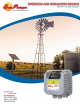
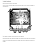
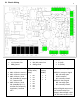
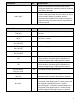
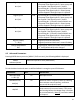
Table Of Contents

Input power line (LINE):
• L1, L2 power line
• GND ground
Output power line (PUMP):
• M1, M2 power line
• GND ground
Pump Signal:
• S+ (red)
• S- (white)
Analog inputs (10 or 15 Vdc):
1. AN1: 4-20 mA: sensor 1
2. AN2: 4-20 mA: sensor 2
3. AN3: 4-20 mA / 0-10
Vdc (settable by jumper
C.C.): external set
4. AN4: 4-20 mA / 0-10
Vdc (settable by C.C.):
trimmer for frequency
regulation / external
set 2
Digital inputs
(Pump start /
stop):
• IN1
• OV
• IN2
• OV
• IN3
• OV
• IN4
• OV
Communication
auxiliary
(RS485):
• S+
• S-
• G
Digital outputs (relays):
RELAY1: pump run signal
NO: normally open
COM: common
NC: normally closed
RELAY2: alarm signal
NO: normally open
NC: normally closed
Relays of digital outputs are
free contacts relays (no
voltage). Max voltage is 250
V AC and max current is 5 A.
3.1 Electric Wiring
5