Sun™ GigaSwift Ethernet Adapter Installation and User’s Guide Sun Microsystems, Inc. 901 San Antonio Road Palo Alto, CA 94303-4900 U.S.A. 650-960-1300 Part No. 816-1702-11 February 2003, Revision A Send comments about this document to: docfeedback@sun.
Copyright 2003 Sun Microsystems, Inc., 4150 Network Circle, Santa Clara, California 95054, U.S.A. All rights reserved. This product or document is distributed under licenses restricting its use, copying, distribution, and decompilation. No part of this product or document may be reproduced in any form by any means without prior written authorization of Sun and its licensors, if any. Third-party software, including font technology, is copyrighted and licensed from Sun suppliers.
Regulatory Compliance Statements Your Sun product is marked to indicate its compliance class: • • • • Federal Communications Commission (FCC) — USA Industry Canada Equipment Standard for Digital Equipment (ICES-003) — Canada Voluntary Control Council for Interference (VCCI) — Japan Bureau of Standards Metrology and Inspection (BSMI) — Taiwan Please read the appropriate section that corresponds to the marking on your Sun product before attempting to install the product.
ICES-003 Class A Notice - Avis NMB-003, Classe A This Class A digital apparatus complies with Canadian ICES-003. Cet appareil numérique de la classe A est conforme à la norme NMB-003 du Canada. ICES-003 Class B Notice - Avis NMB-003, Classe B This Class B digital apparatus complies with Canadian ICES-003. Cet appareil numérique de la classe B est conforme à la norme NMB-003 du Canada.
BSMI Class A Notice The following statement is applicable to products shipped to Taiwan and marked as Class A on the product compliance label.
vi Sun GigaSwift Ethernet Adapter Installation and User’s Guide • February 2003
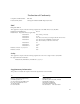
Declaration of Conformity Compliance Model Number: Product Family Name: GCC PCI Sun GigaSwift Ethernet UTP Adapter (X1150A) EMC European Union This equipment complies with the following requirements of the EMC Directive 89/336/EEC: EN55022:1998/CISPR22:1997 Class A EN55024:1998 Required Limits (as applicable): EN61000-4-2 4 kV (Direct), 8 kV (Air) EN61000-4-3 3 V/m EN61000-4-4 1 kV AC Power Lines, 0.5 kV Signal and DC Power Lines EN61000-4-5 1 kV AC Line-Line and Outdoor Signal Lines 2 kV AC Line-Gnd, 0.
viii Sun GigaSwift Ethernet Adapter Installation and User’s Guide • February 2003
Declaration of Conformity Compliance Model Number: Product Family Name: GFC PCI Sun GigaSwift Ethernet MMF Adapter (X1151A) EMC European Union This equipment complies with the following requirements of the EMC Directive 89/336/EEC: EN55022:1998/CISPR22:1997 Class A EN55024:1998 Required Limits (as applicable): EN61000-4-2 4 kV (Direct), 8 kV (Air) EN61000-4-3 3 V/m EN61000-4-4 1 kV AC Power Lines, 0.5 kV Signal and DC Power Lines EN61000-4-5 1 kV AC Line-Line and Outdoor Signal Lines 2 kV AC Line-Gnd, 0.
x Sun GigaSwift Ethernet Adapter Installation and User’s Guide • February 2003
Contents 1. Product Overview 1 Hardware Overview 1 Sun GigaSwift Ethernet MMF Adapter LED Displays 2 Sun GigaSwift Ethernet UTP Adapter LED Displays Patch Requirements 6 Diagnostic Support Installing the Adapter 6 7 9 Installing the Driver Software ▼ 5 5 Key Protocols and Interfaces 2. 3 3 Hardware and Software Requirements Product Features 2 9 To Install Driver Software for Solaris 2.
Rebooting the System 20 Installing the Adapter With Dynamic Reconfiguration ▼ 3.
GigaSwift Ethernet Driver Operating Statistics Reporting the Link Partner Capabilities 5. Configuring VLANs ▼ A. 63 65 To Configure Static VLANs Specifications Connectors 66 69 69 Performance Specifications Physical Characteristics Power Requirements B.
xiv Sun GigaSwift Ethernet Adapter Installation and User’s Guide • February 2003
Figures FIGURE 1-1 Sun GigaSwift Ethernet MMF Adapter 2 FIGURE 1-2 Sun GigaSwift Ethernet UTP Adapter FIGURE 2-1 Connecting the Fiber Optic Cable FIGURE 2-2 Cat-5 Twisted-Pair Cable 16 FIGURE 5-1 Example of Servers Supporting Multiple VLANs with Tagging Adapters 64 FIGURE 5-2 Ethernet Tag Header Format FIGURE A-1 Sun GigaSwift Ethernet MMF Adapter Connector 69 FIGURE A-2 Sun GigaSwift Ethernet UTP Adapter Connector 3 15 66 70 xv
xvi Sun GigaSwift Ethernet Adapter Installation and User’s Guide • February 2003
Tables TABLE 1-1 Front Panel Display LEDs for the MMF Adapter 2 TABLE 1-2 Front Panel Display LEDs for the UTP Adapter 4 TABLE 2-1 Files and Directories on the CD-ROM 10 TABLE 3-1 Device Link Parameters TABLE 3-2 link-clock Capabilities for Link Up 34 TABLE 4-1 ce Driver Parameter, Status, and Descriptions TABLE 4-2 Operational Mode Parameters TABLE 4-3 Read-Write Flow Control Keyword Descriptions TABLE 4-4 Forced Mode Parameter 42 TABLE 4-5 Parameters Defining enable-ipg0 and ipg0 TABL
xviii TABLE A-3 Performance Sepcifications TABLE A-4 Physical Characteristics TABLE A-5 Power Requirements 71 TABLE B-1 Troubleshooting the GigaSwift Ethernet Adapter 70 71 78 Sun GigaSwift Ethernet Adapter Installation and User’s Guide • February 2003
Preface The Sun GigaSwift Ethernet Adapter Installation and User’s Guide provides installation instructions for both the Sun GigaSwift Ethernet UTP adapter and the Sun GigaSwift Ethernet MMF adapter. This manual also describes how to configure the driver software. These instructions are designed for enterprise system administrators with experience installing network hardware and software. How This Book Is Organized Chapter 1, provides a description of the adapter, including hardware and software.
Using UNIX Commands This document may not contain information on basic UNIX® commands and procedures such as shutting down the system, booting the system, and configuring devices.
Shell Prompts Shell Prompt C shell machine_name% C shell superuser machine_name# Bourne shell and Korn shell $ Bourne shell and Korn shell superuser # Related Documentation Application Title PCI Adapter Installation Your system installation or service manual Storage Device Installation Your storage device installation or service manual Dynamic Reconfiguration Installation Sun Enterprise 6x00, 5x00, 4x00, and 3x00 Systems Dynamic Reconfiguration User’s Guide Diagnostic Software SunVTS User
Sun Welcomes Your Comments Sun is interested in improving its documentation and welcomes your comments and suggestions. You can email your comments to Sun at: docfeedback@sun.com Please include the part number (816-1702-11) of your document in the subject line of your email.
CHAPTER 1 Product Overview This chapter provides a description of the Sun GigaSwift Ethernet adapter hardware and software.
Sun GigaSwift Ethernet MMF Adapter The Sun GigaSwift Ethernet MMF adapter is a single-port gigabit Ethernet fiber optics PCI Bus card. It operates in 1000 Mbps Ethernet networks only. FIGURE 1-1 Sun GigaSwift Ethernet MMF Adapter LED Displays Four LEDs are displayed on the front panel of Sun GigaSwift Ethernet MMF adapter. They are labeled on the front panel as shown in TABLE 1-1.
Sun GigaSwift Ethernet UTP Adapter The Sun GigaSwift Ethernet UTP adapter is a single-port gigabit Ethernet copperbased PCI Bus card. It can be configured to operate in 10, 100, or 1000 Mbps Ethernet networks. FIGURE 1-2 Sun GigaSwift Ethernet UTP Adapter LED Displays A total of nine LEDs are displayed on the front panel of the Sun GigaSwift Ethernet UTP adapter. They are labeled on the front panel as shown in TABLE 1-2. The nine LEDs consist of a single purple LED and two sets of four green LEDs.
equivalent to TX and RX of the PHY except that they indicate the state of the MAC instead and can be used for diagnostic purposes to isolate a PHY or a MAC failure on the board.
Hardware and Software Requirements Before using the Sun GigaSwift Ethernet adapter, make sure your system meets the following hardware and software requirements: Hardware and Software Requirements Hardware Sun Ultra™ 5, 10, 60, 80 Sun Enterprise™ 220R, 250, 450, 3000/3500, 4000/4500, 5000/ 5500, 6000/6500/6800, 10000, 15000 Sun Fire™ 280R, V480, V880 Sun Blade™ 1000 OpenBoot PROM Revision 3.x Operating environment Solaris 2.
■ ■ Patch-ID Number 112327-07 for Solaris 2.6 and 7 operating environments Patch-ID Number 111883-13 for Solaris 8 operating environments Install the latest version of the Patch-ID Number for example, the dash number -07 becomes higher with each new version of the patch.
Diagnostic Support ■ ■ User-executable self-test using OpenBoot™ PROM SunVTS diagnostic tool Chapter 1 Product Overview 7
8 Sun GigaSwift Ethernet Adapter Installation and User’s Guide • February 2003
CHAPTER 2 Installing the Adapter This chapter describes how to install the adapter in your system and how to verify that it has been installed correctly.
2. Insert the Sun GigaSwift Ethernet Driver 1.0 Update 1 CD into a CD-ROM drive that is connected to your system. ■ ■ If your system is running Sun Enterprise Volume Manager™, it should automatically mount the CD-ROM to the /cdrom/cdrom0 directory.
3. Install the software packages by typing the following at the command line, replacing the OS_VER with your version (2.
▼ To Install Driver Software for Solaris 2.6 Operating Environments 1. Become superuser. 2. Insert the Sun GigaSwift Ethernet Driver 1.0 CD into a CD-ROM drive that is connected to your system. ■ If your system is running Sun Enterprise Volume Manager™, it should automatically mount the CD-ROM to the /cdrom/cdrom0 directory. ■ If your system is not running Volume Manager, mount the CD-ROM as follows: # mkdir /cdrom # mkdir /cdrom/cdrom0 # mount -F hsfs -o ro /dev/dsk/c0t6d0s2 /cdrom/cdrom0 3.
● To verify patches for Solaris 8 operating environments, type the following. # showrev -p | grep 111883 The patch version should be -13 or greater. ● To verify patches for Solaris 9 operating environments, type the following. # showrev -p | grep 112817 The patch version should be -05 or greater.
Installing the Adapter Without Dynamic Reconfiguration ▼ To Install the Adapter Note – The following instructions describe the basic tasks required to install the adapter. Refer to your system installation or service manual for detailed PCI adapter installation instructions. 1. Halt and power off your system. 2. Power off all of the peripherals connected to your system. 3. Open the system unit. 4. Attach the adhesive copper strip of the antistatic wrist strap to the metal casing of the power supply.
8. Applying even pressure at both corners of the adapter, push the PCI adapter until it is firmly seated in the slot. Caution – Do not use excessive force when installing the adapter into the PCI slot. You may damage the adapter’s PCI connector. If the adapter does not seat properly when you apply even pressure, remove the adapter and carefully reinstall it again. 9. Secure the adapter to the PCI slot using the screw you removed in Step 6. 10. Detach the wrist strap and close the system unit. 11.
FIGURE 2-2 ▼ Cat-5 Twisted-Pair Cable To Verify the Installation After you have installed the Sun GigaSwift Ethernet adapter, but before you boot your system, perform the following tasks to verify the installation. Refer to the Solaris Handbook for Sun Peripherals manual or your Solaris documentation for the detailed instructions. Note – Verification is not required if your system supports dynamic reconfiguration (DR). 1.
2. List the network devices on your system. ok show-nets Use the show-nets command to list the system devices. You should see the full path name of the network devices, similar to the Ultra 30 system example below. In this example, the network@4 device is the Sun GigaSwift Ethernet adapter and the network@1,1 is the onboard Ethernet device.
4. View the.properties file for a list of device properties. It might be difficult to tell if the devices on your network are GigaSwift Ethernet devices or other network interface cards. The.properties command displays the specific information about the installed adapter. At the ok prompt, use the .properties command to make sure that the device you just installed is connected to the network. Your output may look different from the following example: ok .
The phy-type will have its value assigned as follows: Media type phy-type Fiber pcs Copper mif Note – If you are going to set the local-mac-address property, note the local-mac-address of your device at this time. See “Setting the local-macaddress Property” on page 19 for more information. Setting the local-mac-address Property Note – Setting the local-mac-address property is only required if you will be booting from the network.
▼ To Set the GigaSwift Ethernet Device Primary Boot Device Use this procedure only if you want the GigaSwift Ethernet device to be your primary boot device. 1. List the network devices on your system. ok show-nets a) /pci@1f,2000/pci@1/network@4 b) /pci@1f,4000/network@1,1 q) NO SELECTION Enter Selection, q to quit: q 2.
Installing the Adapter With Dynamic Reconfiguration If you have a Sun Enterprise system that supports dynamic reconfiguration (DR), you do not have to reboot your system after installing the adapter. The process of adding and configuring an adapter with DR involves (1) connecting the attachment point and (2) configuring its occupant. In most cases, the cfgadm(1M) command can perform both steps at once. ▼ To Install an Adapter in a Dynamic Reconfiguration System 1.
2. If the status of the slot is not “empty” or “disconnected”, type: # cfgadm -c disconnect sysctrl#:slot# where the sysctrl# = 0 for the Enterprise 10000 and slot#= the slot available for the adapter. For example, if you were installing the adapter into slot #3 on an Enterprise 10000, you would type the following: # cfgadm -c disconnect sysctrl0:3 3. Physically insert the adapter into the slot and look for an acknowledgement on the console, such as, “name board inserted into slot3.
Now the system is also aware of the usable devices which reside on the adapter and all devices may be mounted or configured to be used. If the command fails to connect and configure the adapter and slot (the status should be shown as “configured” and “ok”), do the connection and configuration as separate steps: a.
24 Sun GigaSwift Ethernet Adapter Installation and User’s Guide • February 2003
CHAPTER 3 Network Configuration This chapter describes how to edit the network host files after the adapter has been installed on your system.
Use the ifconfig command to assign an IP address to the network interface. Type the following at the command line, replacing ip_address with the adapter’s IP address: # ifconfig ce0 plumb ip_address up Refer to the ifconfig(1M) man page and the Solaris documentation for more information. ■ If you want a set-up that will remain the same after you reboot, create an /etc/hostname.cenumber file, where number corresponds to the instance number of the ce interface you plan to use.
3. Create an appropriate entry in the /etc/hosts file for each active ce interface. For example: # cat /etc/hosts # # Internet host table # 127.0.0.1 localhost 129.144.10.57 zardoz loghost 129.144.11.83 zardoz-11 Setting Up a GigaSwift Ethernet Network on a Diskless Client System Before you can boot and operate a diskless client system across a gigabit Ethernet network, you must first install the GigaSwift Ethernet software packages into the root directory of the diskless client.
2. Insert the Sun GigaSwift Ethernet Driver 1.0 Update 1 CD into the server’s CD-ROM drive. The CD should automatically mount to the /cdrom/cdrom0 directory. If the CD did not get mounted to this directory, refer to “Installing the Driver Software” on page 9 for mounting instructions. 3. Use the pkgadd -R command to install the three GigaSwift Ethernet software packages to the diskless client’s root directory on the server. You will need to install the SUNWced.
Installing the Solaris Operating Environment Over a GigaSwift Ethernet Network The Solaris Advanced Installation Guide describes the full procedure for installing the Solaris operating environment over the network. The procedure below assumes that you have created an install server, which contains the image of the Solaris CD, and that you have set up the client system to be installed over the network.
2. Find the root directory of the client system. The client system’s root directory can be found in the install server’s /etc/bootparams file. Use the grep command to search this file for the root directory. # grep client_name /etc/bootparams client_name root=server_name:/netinstall/Solaris_2.7/Tools/Boot install=server_name:/netinstall boottype=:in rootopts=:rsize=32768 In the example above, the root directory for the Solaris 7 client is /netinstall.
6. Shut down and halt the client system. Use the shutdown command to display the OpenBoot (ok) prompt. # shutdown -i0 -g0 -y . . . (shutdown command messages omitted) . . . ok 7. At the ok prompt, use the show-nets command to find the device path of the GigaSwift Ethernet device. The show-nets command lists the system devices. You should see the full path name of the network device, similar to the example below. In this example, the network@4 device is the Sun GigaSwift Ethernet adapter.
■ Booting in non-Auto-Negotiated verbose mode at 100 Mbps full duplex: ok boot /pci@1f,4000/network@4:speed=100,duplex=full, -v ■ Booting in non-Auto-Negotiated verbose mode at 1000 Mbps half duplex linkclock master: ok boot /pci@1f,4000/network@4:speed=1000,duplex=half,link-clock=master Note – For link to be successfully established the link partner must be configured to 1000 Mbps half duplex link-clock slave. 9. Proceed with the Solaris operating environment installation.
11. Confirm that the network host files have been configured correctly during the Solaris installation. Although the Solaris software installation creates the client’s network configuration files, you may need to edit these files to match your specific networking environment. See “Configuring the Network Host Files” on page 25 for more information about editing these files.
TABLE 3-1 Device Link Parameters Device Parameters Device Link Capability speed duplex link-clock autoneg 1000fdx 1000hdx 100fdx 100hdx 10fdx 10hdx 1000 full master/slave 0 0 0 0 0 0 0 1000 half master/slave 0 1 0 0 0 0 0 1000 full auto 1 1 1 1 1 1 1 1000 half auto 1 0 1 1 1 1 1 1000 auto 1 1 1 1 1 1 1 1 1 1 1 1 1 1 1 1 1 1 1 1 1 1000 1000 auto 100 full N/A 0 0 0 1 0 0 100 half N/A 0 0 0 0 1 0 100 auto N/A 1
Following are examples showing the usage of the boot net command line with device parameters specified: To attempt to force the link-up while advertising 100 Mbps full duplex capability to the link partner: # boot net:speed=100,duplex=full, To attempt to force link-up while advertising 1000 Mbps full duplex link-clock master capibility to the link partner: # boot net:speed=1000,duplex=full,link-clock=master, Note – The link partner must be configured as link-clock slave.
36 Sun GigaSwift Ethernet Adapter Installation and User’s Guide • February 2003
CHAPTER 4 Configuring Driver Parameters This chapter describes how to configure the driver parameters used by the Sun GigaSwift Ethernet adapter.
Note – The syntax for the Sun GigaSwift Ethernet driver parameters has changed. The syntax for parameters formerly included an underscore, for example, adv_autoneg_cap. The current syntax uses a dash instead, for example, adv-autoneg-cap. During the transition phase, either format is acceptable. However, be sure to check the Platform Notes: Sun GigaSwift Ethernet Device Driver in your version of the Solaris operating environment.
TABLE 4-1 ce Driver Parameter, Status, and Descriptions (Continued) Parameter Status Description red-dv4to6k Read and write Random early detection and packet drop vectors red-dv6to8k Read and write Random early detection and packet drop vectors red-dv8to10k Read and write Random early detection and packet drop vectors red-dv10to12k Read and write Random early detection and packet drop vectors tx-dma-weight Read and write PCI Interface parameter rx-dma-weight Read and write PCI Interfac
TABLE 4-2 Operational Mode Parameters (Continued) Parameter Description adv-100hdx-cap Local interface capability advertised by the hardware 0 = Not 100 Mbit/sec half-duplex capable 1 = 100 Mbit/sec half-duplex capable (default) adv-10fdx-cap Local interface capability advertised by the hardware 0 = Not 10 Mbit/sec full-duplex capable 1 = 10 Mbit/sec full-duplex capable (default) adv-10hdx-cap Local interface capability advertised by the hardware 0 = Not 10 Mbit/sec half-duplex capable 1 = 10 Mbit/
TABLE 4-3 provides flow control keywords and describes their function. TABLE 4-3 Read-Write Flow Control Keyword Descriptions Keyword Description adv-asmpause-cap The adapter supports asymmetric pause, which means it can pause only in one direction. 0=Off (default) 1=On adv-pause-cap This parameter has two meanings depending on the value of adv-asmpause-cap. (Default=0) If adv-asmpause-cap = 1 while adv-pause-cap = 1 pauses are received.
Gigabit Link Clock Mastership Controls The concept of link clock mastership introduced with one gigabit twisted-pair technology. This concept requires one side of the link to be the master that provides the link clock and the other to be the slave that uses the link clock. Once this relationship is established the link is up, and data can be communicated. Two Physical layer parameters control whether your side is the master or the slave or whether mastership is negotiated with the link partner.
If enable-ipg0 is disabled, the value of ipg0 is ignored and no additional delay is set. Only the delays set by ipg1 and ipg2 will be used. Disable enable-ipg0 if other systems keep sending a large number of back-to-back packets. Systems that have enable-ipg0 set might not have enough time on the network. You can add the additional delay by setting the ipg0 parameter from 0 to 255, which is the media byte time delay. TABLE 4-5 defines the enable-ipg0 and ipg0 parameters.
Interrupt Parameters TABLE 4-7 describes the receive interrupt blanking values. TABLE 4-7 44 RX Blanking Register for Alias Read Field Name Values Description rx-intr-pkts 0 to 511 Interrupt after this number of packets have arrived since the last packet was serviced. A value of zero indicates no packet blanking. (Default=8) rx-intr-time 0 to 524287 Interrupt after 4.5 microseconds ticks have elapsed since the last packet was serviced. A value of zero indicates no time blanking.
Random Early Drop Parameters TABLE 4-8 describes the RX random early detection 8-bit vectors, which allows you to enable random early drop (RED) thresholds. When received packets reach the RED range packets are dropped according to the preset probability. The probability should increase when the FIFO level increases. Control packets are never dropped and are not counted in the statistics.
PCI Bus Interface Parameters These parameters allow you to modify PCI interface features to gain better PCI performance for a given application. TABLE 4-9 PCI Bus Interface Parameters Parameter Description tx-dma-weight Determine the multiplication factor for granting credit to the TX side during a weighted round robin arbitration. Values are 0 to 3. (Default=0) Zero means no extra weighting. The other values are power of 2 extra weighting, on that traffic.
Setting ce Driver Parameters You can set the ce device driver parameters in two ways: ■ ■ Using the ndd utility Using the ce.conf file If you use the ndd utility, the parameters are valid only until you reboot the system. This method is good for testing parameter settings. To set parameters so they remain in effect after you reboot the system, create a /platform/sun4u/kernel/drv/ce.conf file and add parameter values to this file when you need to set a particular parameter for a device in the system.
▼ To Specify Device Instances for the ndd Utility Before you use the ndd utility to get or set a parameter for a ce device, you must specify the device instance for the utility. 1. Check the /etc/path_to_inst file to identify the instance associated with a particular device.
Using the ndd Utility in Noninteractive Mode This section describes how to modify and display parameter values. ● To modify a parameter value, use the -set option.
● To list all the parameters supported by the ce driver, type ndd /dev/ce. (See TABLE 4-1 through TABLE 4-11 for parameter descriptions.
▼ To Disable Autonegotiation Mode If your network equipment does not support autonegotiation, or if you want to specify your network speed, you can set autonegotiation to off on the ce device. Note – Disabling autonegotiation mode can cause collisions. 1.
The man pages for prtconf(1M) and driver.conf(4) include additional details. The next procedure shows an example of setting parameters in a ce.conf file. ▼ To Set Driver Parameters Using a ce.conf File 1. Obtain the hardware path names for the ce devices in the device tree. a. Check the /etc/driver_aliases file to identify the name associated with a particular device: # grep ce /etc/driver_aliases ce "pci108e,abba" b.
■ unit-address = “0” In the third line in the previous example: ■ parent = “pci@5” ■ unit-address = “1” 2. Set the parameters for the above devices in the /platform/sun4u/kernel/drv/ce.conf file. In the following example, the adv_autoneg_cap and adv_1000fdx_cap parameters are set for all Sun GigaSwift Ethernet devices. (See the driver.conf(4) man page for more information.
■ Then you had to get the link status: # ndd -get /dev/hme link-status 1 Starting with the Sun GigaSwift Ethernet adapter in the Solarlis 9 operating environment this method of determining the link status is discouraged, and in some cases, it is removed completely as a driver feature. The new improved approach moves all read-only parameters from the ndd options into kstat. This simplifies getting link status information by allowing you to do it with one simple command.
TABLE 4-10 describes the read-only Media Independent Interface (MII) capabilities. These parameters define the capabilities of the hardware. The Gigabit Media Independent Interface (GMII) supports all of the following capabilities.
Reporting the Link Partner Capabilities TABLE 4-11 describes the read-only link partner capabilities.
TABLE 4-12 describes the netstat -k transmit and receive parameters: TABLE 4-12 Transmit and Receive Parameters Parameter Description xcvr_inits Number of Physical layer re-initializations every time you change link parameters using NDD this increments. rev_id Revision ID of the GigaSwift Ethernet device useful for recognition of device being used in the field. xcvr_addr GMII/MII Physical layer device address for management interface.
TABLE 4-12 58 Transmit and Receive Parameters Parameter Description rx_new_hdr_pgs Number of pages that were filled with packets less than 256 bytes that got replaced during reception. rx_new_mtu_pgs Number of pages that were filled with packets greater than 256 bytes and less than 1514 that got replaced during reception. rx_new_nxt_pgs Number of pages that contained packets that were split across pages that got replaced during reception.
▼ To Check Link Partner Settings ● If you are running Solaris 2.
CODE EXAMPLE 4-1 Output from kstat Command (Continued) # kstat ce0 cap_10fdx cap_10hdx cap_asmpause cap_autoneg cap_pause code_violations collisions crc_err crtime excessive_collisions first_collision ierrors ifspeed ipackets ipackets64 ipackets_cpu00 ipackets_cpu01 ipackets_cpu02 ipackets_cpu03 late_collisions lb_mode length_err link_T4 link_asmpause link_duplex link_pause link_speed link_up lp_cap_1000fdx lp_cap_1000hdx lp_cap_100T4 lp_cap_100fdx lp_cap_100hdx lp_cap_10fdx lp_cap_10hdx lp_cap_asmpause l
CODE EXAMPLE 4-1 Output from kstat Command (Continued) # kstat ce0 opackets64 pci_bad_ack_err pci_dmarz_err pci_dmawz_err pci_drto_err pci_err pci_parity_err pci_rma_err pci_rta_err peak_attempts promisc qos_mode rbytes rbytes64 rev_id rx_allocb_fail rx_hdr_drops rx_hdr_pkts rx_inits rx_len_mm rx_msgdup_fail rx_mtu_drops rx_mtu_pkts rx_new_hdr_pgs rx_new_mtu_pgs rx_new_nxt_pgs rx_new_pages rx_no_buf rx_no_comp_wb rx_nocanput rx_nxt_drops rx_ov_flow rx_pkts_dropped rx_rel_bit rx_rel_flow rx_split_pkts rx_t
CODE EXAMPLE 4-1 Output from kstat Command (Continued) # kstat ce0 tx_inits tx_max_desc tx_max_pend tx_msgdup_fail tx_no_desc tx_nocanput tx_queue0 tx_queue1 tx_queue2 tx_queue3 tx_starts tx_uflo xcvr_addr xcvr_id xcvr_inits xcvr_inuse 0 0 0 0 0 0 3 0 0 0 0 0 1 2121809 1 1 Additional Uses for the kstat Command ● Use the kstat command to discover link partner capabilities.
● Use the kstat command to discover link settings.
64 Sun GigaSwift Ethernet Adapter Installation and User’s Guide • February 2003
CHAPTER 5 Configuring VLANs This chapter explains VLANs in detail and provides configuration instructions and examples. ■ VLANs: Virtual Local Area Networks (VLANs) are commonly used to split up groups of network users into manageable broadcast domains, to create logical segmentation of workgroups, and to enforce security policies among each logical segment. With multiple VLANs on an adapter, a server with a single adapter can have a logical presence on multiple IP subnets.
Although VLANs are commonly used to create individual broadcast domains and/ or separate IP subnets, it is sometimes useful for a server to have a presence on more than one VLAN simultaneously. Several Sun products support multiple VLANs on a per port or per interface basis, allowing very flexible network configurations. FIGURE 5-1 shows an example network that uses VLANs .
■ The Main Server is a high-use server that needs to be accessed from all VLANs and IP subnets. The server has an Sun GigaSwift Ethernet adapter installed. All three IP subnets are accessed via the single physical adapter interface. The server is attached to one of the SunSwitch’s Gigabit Ethernet ports, which is configured for VLANs 1, 2, and 3. Both the adapter and the connected SunSwitch port have tagging turned on.
Tagging an Ethernet frame requires the addition of a tag header to the frame. The header is inserted immediately following the Destination MAC address and the Source MAC address. The tag header consists of two bytes of Ethernet Tag Protocol Identifier (TPID, 0x8100) and two bytes of Tag Control Information (TCI). FIGURE 5-2 shows the Ethernet Tag Header format.
2. Use the ifconfig(1M) to configure a VLAN virtual device, for example: # ifconfig ce123000 plumb up # ifconfig ce224000 plumb up The output of ifconfig -a on a system having VLAN devices ce123000 and ce224000: # ifconfig -a lo0: flags=1000849 mtu 8232 index 1 inet 127.0.0.1 netmask ff000000 hme0: flags=1000843 mtu 1500 index 2 inet 129.144.131.91 netmask ffffff00 broadcast 129.144.131.
68 Sun GigaSwift Ethernet Adapter Installation and User’s Guide • February 2003
APPENDIX A Specifications This appendix lists the specifications for the Sun GigaSwift Ethernet adapter. It contains the following sections: ■ ■ ■ ■ “Connectors” on page 69 “Performance Specifications” on page 70 “Physical Characteristics” on page 71 “Power Requirements” on page 71 Connectors FIGURE A-1 shows the connector for the Sun GigaSwift Ethernet MMF adapter. FIGURE A-1 Sun GigaSwift Ethernet MMF Adapter Connector TABLE A-1 lists the characteristics of the SC connector (850 nm).
FIGURE A-2 shows the connector for the Sun GigaSwift Ethernet UTP adapter. FIGURE A-2 Sun GigaSwift Ethernet UTP Adapter Connector Table A-2 lists the characteristics of the Cat-5 Connector used by the Sun GigaSwift Ethernet UTP adapter.
Physical Characteristics TABLE A-4 Physical Characteristics Dimension Measurement Length 6.8 inches Width 4.2 inches Power Requirements TABLE A-5 Power Requirements Specification Measurement Maximum power consumption 12 watts (MMF) 15 watts (UTP) Voltage 3.
72 Sun GigaSwift Ethernet Adapter Installation and User’s Guide • February 2003
APPENDIX B Diagnostic Software and Troubleshooting Issues This appendix provides an overview of the SunVTS diagnostic application and instructions for testing the adapter using the onboard FCode self-test. There is also a section outlining some common troubleshooting issues.
Using the OpenBoot PROM FCode SelfTest The following tests are available to help identify problems with the adapter if the system does not boot. You can invoke the FCode self-test diagnostics by using the OpenBoot user interface test or test-all commands. If you encounter an error while running diagnostics, appropriate messages will be displayed. Refer to the appropriate OpenBoot Command Reference Manual for more information on the test and test-all commands.
4. Type show-nets to display the list of devices. You should see a list of devices, similar to the example below, specific to the adapter: ok show-nets a) /pci@1f,0/pci@1/network@4 b) /pci@1f,0/pci@1,1/network@1,1 q) NO SELECTION Enter Selection, q to quit: 5.
7. Set the auto-boot? configuration parameter to true. ok setenv auto-boot? true 8. Reset and reboot the system. Refer to the appropriate OpenBoot Command Reference Manual for more information. Troubleshooting Issues Known Incompatibilities with Pre-IEEE 802.3z Network Switches You might experience interoperability issues when using the Sun GigaSwift Ethernet adapter with the SunSwitch switch, the Alteon ACE 110 switch, or other pre- or non-IEEE 802.3z standard compliant network equipment.
2. At the Main# prompt, type cfg to display the Configuration menu and prompt (Configuration#). >> Main# cfg [Configuration Menu] sys - System-wide parameter menu port - Port configuration menu ip - IP addressing menu vlan - VLAN configuration menu stp - Spanning Tree menu snmp - SNMP menu setup - Step by step configuration set up dump - Dump current configuration to script file >> Configuration# 3. Type the following to disable autonegotiation on a GigaSwift Ethernet port.
2. Set the adv-autoneg-cap parameter to 0. Note – See Chapter 4 for the default values of these parameters and for instructions on how to set these parameters. Failure to Configure GigaSwift Ethernet Instance If your machine fails to configure a GigaSwift Ethernet instance, yet prtconf indicates the adapter is present, the problem may be due to residue adapter instances in the path_to_inst file. To solve this problem, open the path_to_inst file for editing and remove the lines containing ce device path.
TABLE B-1 Troubleshooting the GigaSwift Ethernet Adapter (Continued) Problem Description Solution System panics in Solaris 7 11/99 environment when CPR attempts to suspend a nonsuspendable thread The GigaSwift Ethernet driver uses certain not suspendable kernel threads. When CPR attempts to suspend the driver, the system panics. Currently, CPR is supported only in Sun desktop systems (for example, Ultra 10 and Ultra 60). • Turn off CPR. • A CPR fix is incorporated in Solaris 8.
80 Sun GigaSwift Ethernet Adapter Installation and User’s Guide • February 2003
Index SYMBOLS E .properties command, 18 .properties file, 18 /etc/hostname.
checking, 58 local-mac-address property, 19 T M V MAC address, 19 mac-address property, 19 Media Access Control (MAC), 19 verify the installation, 16 virtual device, 67 VLAN ID, 65 VLAN naming format, 66 VLANs, 63 to set, 19 N ndd utility, 48 nettest diagnostic, 73 NVRAM configuration, 19 O operational mode parameters, 39 P parameter values how to modify and display, 49 parameters and settings, 38 R random early detection register, 45 receive interrupt blanking values, 39, 44 S setting ce driver