StorageTek TIMBERWOLF™ 9740 Tape Library Hardware Operator’s Guide 95693 Revision: P
TimberWolf 9740 Tape Library Hardware Operator’s Guide
Copyright 2006 Sun Microsystems, Inc., 4150 Network Circle, Santa Clara, California 95054, U.S.A. All rights reserved. Sun Microsystems, Inc. has intellectual property rights relating to technology that is described in this document. In particular, and without limitation, these intellectual property rights may include one or more of the U.S. patents listed at http://www.sun.com/patents and one or more additional patents or pending patent applications in the U.S. and in other countries.
Summary of Changes EC Date Revision Description 111257 November 1999 H Changes as noted in this revision. 111486 May 2000 J Changes as noted in this revision. 111516 August 2000 K Changes as noted in this revision. 111545 October 2000 L Changes as noted in this revision. 111714 December 2001 M Changes as noted in this revision. 114111 September 2005 N Changes as noted in this revision.
iv Revision P 95693
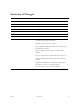
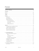
Contents Summary of Changes . . . . . . . . . . . . . . . . . . . . . . . . . . . . . . . . . . . . . . . . . . . . . . . . . . . . iii Contents . . . . . . . . . . . . . . . . . . . . . . . . . . . . . . . . . . . . . . . . . . . . . . . . . . . . . . . . . . . . . . . . v Figures . . . . . . . . . . . . . . . . . . . . . . . . . . . . . . . . . . . . . . . . . . . . . . . . . . . . . . . . . . . . . . . viii Tables . . . . . . . . . . . . . . . . . . . . . . . . . . . . . . . . . . . . . . . . . . . . . .
Contents Tape Drives and Cabinets . . . . . . . . . . . . . . . . . . . . . . . . . . . . . . . . . . . . . . . . . . . . . . . . . . . . . . Controller Transport Units . . . . . . . . . . . . . . . . . . . . . . . . . . . . . . . . . . . . . . . . . . . . . . . . . . . . . Operator Panel . . . . . . . . . . . . . . . . . . . . . . . . . . . . . . . . . . . . . . . . . . . . . . . . . . . . . . . . . . . . . . . . . . . Setting the SCSI Address . . . . . . . . . . . . . . . . . . . . . . . . . . . . . . .
Contents Controller Transport Units . . . . . . . . . . . . . . . . . . . . . . . . . . . . . . . . . . . . . . . . . . . . . . . . . . . . . . . . . 9490 . . . . . . . . . . . . . . . . . . . . . . . . . . . . . . . . . . . . . . . . . . . . . . . . . . . . . . . . . . . . . . . . . . . . . . . . SD-3 . . . . . . . . . . . . . . . . . . . . . . . . . . . . . . . . . . . . . . . . . . . . . . . . . . . . . . . . . . . . . . . . . . . . . . . . Power Switch . . . . . . . . . . . . . . . . . . . . . . . . .
Figures Figure 1-1. External Components . . . . . . . . . . . . . . . . . . . . . . . . . . . . . . . . . . . . . . . . . . . . . . . . . . . . . . . 1-2 Figure 1-2. Robot Components . . . . . . . . . . . . . . . . . . . . . . . . . . . . . . . . . . . . . . . . . . . . . . . . . . . . . . . . . 1-3 Figure 2-1. LSM Power Switch . . . . . . . . . . . . . . . . . . . . . . . . . . . . . . . . . . . . . . . . . . . . . . . . . . . . . . . . . . 2-1 Figure 2-2.
Tables Table 1-1. LSM Specifications . . . . . . . . . . . . . . . . . . . . . . . . . . . . . . . . . . . . . . . . . . . . . . . . . . . . . . . . . . . 1-6 Table 3-1. Playground Cartridge Locations . . . . . . . . . . . . . . . . . . . . . . . . . . . . . . . . . . . . . . . . . . . . . . . 3-19 Table A-1. 9490 Cartridge Environmental Specifications . . . . . . . . . . . . . . . . . . . . . . . . . . . . . . . . . . . A-18 Table A-2. SD-3 Cartridge Environmental Specifications . . . . . . . . . . . . . .
Tables x Revision P 95693
Preface This guide describes how to operate the TimberWolf 9740 Library Storage Module (LSM). Most of the information in this guide pertains to the hardware. Note: Refer to the appropriate publications for specific information about the controller transport units, tape drives, software commands, and console messages. This guide is intended primarily for data center operators who operate the LSM. System programmers and computer system administrators might also find the information in this guide useful.
■ Alert Messages Alert messages call your attention to information that is especially important or that has a unique relationship to the main text or graphic. Note: A note provides additional information that is of special interest. A note might point out exceptions to rules or procedures. A note usually, but not always, follows the information to which it pertains.
■ Additional Information Sun Microsystems, Inc. (Sun) offers several methods for you to obtain additional information. Sun’s External Web Site Sun’s external Web site provides marketing, product, event, corporate, and service information. The external Web site is accessible to anyone with a Web browser and an Internet connection. The URL for the external Web site is: http://www.sun.com The URL for StorageTek™ brand-specific information is: http://www.sun.
xiv Revision P 95693
Notices Please read the following compliance and warning statements for this product. CAUTION: Potential equipment damage: Cables that connect peripherals must be shielded and grounded; refer to descriptions in the cable instruction manuals. Operation of this equipment with cables that are not shielded and not correctly grounded might result in interference to radio and TV reception. Changes or modifications to this equipment that are not expressly approved in advance by StorageTek will void the warranty.
■ Japanese Compliance Statement The following compliance statement in Japanese pertains to VCCI EMI regulations: English translation: This is a Class A product based on the Technical Requirement of the Voluntary Control Council for Interference by Information Technology (VCCI). In a domestic environment, this product may cause radio interference, in which case the user may be required to take corrective actions.
■ Internal Code License Statement The following is the Internal Code License Agreement from Sun StorageTek: NOTICE INTERNAL CODE LICENSE PLEASE READ THIS NOTICE CAREFULLY BEFORE INSTALLING AND OPERATING THIS EQUIPMENT. THIS NOTICE IS A LEGAL AGREEMENT BETWEEN YOU (EITHER AN INDIVIDUAL OR ENTITY), THE END USER, AND STORAGE TECHNOLOGY CORPORATION (“STORAGETEK”), THE MANUFACTURER OF THE EQUIPMENT.
information is not otherwise readily available); or (iii) sublicense, assign, or lease the Internal Code or permit another person to use such Internal Code, or any copy of it. If you need a backup or archival copy of the Internal Code, StorageTek, or your authorized StorageTek distributor or reseller, will make one available to you, it being acknowledged and agreed that you have no right to make such a copy. 5.
General Information 1 This chapter describes the library storage module (LSM) for an automated cartridge system (ACS). An ACS is a removable media, robotic system that mounts cartridges into storage cells, tape drives, cartridge access port (CAP), or cartridge exchange mechanism (CEM). Figure 1-1 on page 1-2 and Figure 1-2 on page 1-3 show the location of the major components for the LSM.
Library Storage Module Components Figure 1-1. External Components (C62619) CARTRIDGE DRIVE OR 9741 DRIVE CABINET LOCATION OPERATOR PANEL DOOR LATCHES 2ND LSM LOCATION FOR A CEM INSTALLATION EXPANSION DOOR POWER SWITCH LOCATION CARTRIDGE ACCESS PORT RIGHT FRONT DOOR C62619 Robot Figure 1-2 on page 1-3 shows the robot components. The robot is a mechanism that moves cartridges between storage cells, CTUs, tape drives, CAP, or CEM. The robot consists of the Z column assembly, hand, and camera assembly.
Library Storage Module Components Figure 1-2. Robot Components (C62012) Z MOTOR THETA MOTOR CAMERA HAND STORAGE CELLS Z COLUMN Z CARRIAGE C62012 The camera assembly on the hand reads the cartridge volume serial numbers (VOLSERs) during audits, but is not used to locate cartridges during robotic moves. An audit occurs when: • • • • You power-on the LSM. You open and close an LSM door. You press the IPL (initial program load) button on the LSM.
Library Storage Module Components Cartridge Access Port The cartridge access port (CAP) is a storage area where you add cartridges to or remove cartridges from an LSM. The CAP is located on the right front door. LSMs are shipped with the type of CAP that allows you to place 14 cartridges, one at a time, into the cells, or with a CAP that allows you to place a preloaded 10-cartridge magazine into the CAP. Note: The 10-cell cartridge magazine holds DLT cartridges.
Cartridge Drives and Cabinets ■ Cartridge Drives and Cabinets The cartridge drive attaches to the rear of the LSM and contains: • • Two or four 9490 (TimberLine) CTUs One to four SD-3 (RedWood) CTUs The 9741 or 9741E drive cabinets attach to the rear of the LSM and contains: • • • One to ten Digital Linear Tape (DLT) drives One to ten T9840 Tape Drives One to ten T9940 Tape Drives Each CTU or tape drive holds the cartridge for read/write operations.
LSM Specifications ■ LSM Specifications Table 1-1 lists the LSM specifications: Table 1-1.
Controls and Indicators 2 This chapter shows and describes the power switch and operator panel for the LSM. It also describes how to set the SCSI address as well as the maximum usage count of the cleaning cartridges. Refer to the controller transport unit or tape drive operator guides for information about operating those units. ■ Power Switch The LSM power switch is a circuit breaker located in the lower right corner of the right front door of the LSM. The switch provides power to the LSM only.
Power Switch Tape Drives and Cabinets Drives that are housed in the standard and expanded (9741 and 9741E) Drive Cabinet each have their own power supply that attaches to a power strip at the base of the cabinet. To power down drives in the 9741/9741E Drive Cabinet the circuit breaker that provides power to the drives must be switched off. Do the same to power off the LSM.
Operator Panel ■ Operator Panel The operator panel is mounted to the right front door of the LSM. The panel contains function keys (also referred to as softkeys) and indicators, plus a twoline display. The operator panel displays LSM status, configuration, test sequences, and error information. Figure 2-3 on page 2-4 shows the panel and describes each item. Use the operator panel to: • Resolve machine problems If an error occurs, a fault symptom code (FSC) is displayed.
Setting the SCSI Address Figure 2-3. Operator Panel Function Keys, Indicators, and Displays (C62014) IPL SERVICE REQ (OPERATOR PANEL DISPLAY) MENU PROCESSOR ACTIVE INTERFACE ACTIVE RESET EXECUTE IPL Initiates the download from the diskette. The IPL sequence consists of PROM tests, boot tests, and machine initialization. RESET DESIGNED FOR CSE USE ONLY! NOT an operator activity. Initiates a dump. OPERATOR PANEL DISPLAY Displays machine status and menu information.
Setting the SCSI Address Figure 2-4.
Setting the SCSI Address Figure 2-5. Setting the SCSI Address (C62016) IPL PRESSED After pressing the execute softkey, there will be a momentary delay before this screen appears. Test Screens Download BT0.X SCSI host options are ID 0 through 7 for the PRS card or 0 through 15 for the PRW card. Q Off/On Bus options for drives 1-9 only appear if those drives are installed and configured and after the preceding drive has been assigned an ID. Execute BT0.
Operating the LSM 3 This chapter contains the procedures for: • • • • Powering-on or IPLing the LSM Powering-off the LSM Operating in automated mode Operating in manual mode When the machine is controlled by the host, refer to your software publications and enter the command from the operator console to do the desired activity. ■ Powering-on or IPLing the LSM To power-on or IPL the LSM, lift the power switch at the bottom right corner of the right front door of the LSM.
Operating the LSM in Automated Mode ■ Operating the LSM in Automated Mode When the LSM is online and operating in automated mode, it performs many tasks that you would otherwise perform manually.
Operating the LSM in Automated Mode 4. Close the CAP. The lock automatically engages. Notes: • The host software determines what happens when you enter a cartridge upside down or with an unreadable label. Under normal conditions, the camera on the hand audits the CAP and recognizes that a cartridge is present, but the hand does not move it. You must remove the cartridge from the CAP and correct the problem. • For some systems, you are prompted to type in a label number when no VOLSER is read.
Operating the LSM in Automated Mode Ejecting Cartridges through the CAP Refer to your specific software publications for instructions about having the robot insert the desired cartridges into the CAP. To eject cartridges through the CAP: 1. Enter the VOLSERs of the cartridges you want ejected at the operator console. The robot will retrieve them and insert them into the CAP. 2. If the operator panel displays ONLINE CAP UNLK DISABLD, the CAP is locked by the host.
Cleaning Drives in the LSM ■ Cleaning Drives in the LSM Drive cleaning can be initiated either by the operator or by the backup application. The following information describes the functions the operator needs to perform to clean the drives. Operator-initiated cleaning is handled in one of two ways: • • For a SCSI interface For a serial interface Before attempting to clean any drives in the LSM, make sure you know what type of interface (control path) is installed at your site: SCSI or serial.
Cleaning Drives in the LSM Setting the Cleaning Cartridge Usage Count You can use the operator panel to set the maximum number of times a cartridge can be used to make sure that it is effective. Remember that each drive’s cartridge has a maximum number of cleans, and must be replaced when it expires. See Figure 3-2 for the menu block diagrams to set the usage count. Figure 3-2.
Cleaning Drives in the LSM Replacing Cleaning Cartridges When an LSM operating in an SCSI control path environment is in AUTO CLEAN mode, the only method to use to replace an expired cleaning cartridge is by selecting the Change Cln Cart utility from the main operator panel menu and following these instructions. Notes: • Do not load cleaning cartridges through the door of the LSM because the cleaning usage will not increment.
Cleaning Drives in the LSM Serial Interface If your control path is serial, these items are true: • You do not have the option of using the AUTO CLEAN function from the operator panel. • All drive cleaning is managed by and controlled through the host. The manner which ACSLS (Automated Cartridge System Library Software) handles automatic cleaning operations is defined in the ACSLS 5.3x System Administrator’s Guide, PN 34767.
Cleaning Drives in the LSM To unlock the CAP: 1. Press EXECUTE on the operator panel. a. The operator panel displays ONLINE CAP UNLK PENDING. b. The hand unlocks the CAP. c. The operator panel displays ONLINE CAP UNLOCKED. 2. Open the CAP to gain access to the cells. 3. Remove the cartridges and store them outside the LSM, or remove the magazine from the CAP. Then remove the cartridges from the magazine and store them outside the LSM. 4. Close the CAP. The lock automatically engages.
Operating in Manual Mode ■ Operating in Manual Mode When an LSM is offline, you might be: • • • • • • Opening the LSM front doors Moving the robot Locating a cartridge in the storage cells Mounting and dismounting a cartridge Removing a cartridge from the hand Returning the LSM to online status The following information describes how to perform these activities. Opening the LSM Front Doors You must open the right front door, then the left front door to perform manual operations.
Operating in Manual Mode Figure 3-3.
Operating in Manual Mode Moving the Robot After opening the LSM doors, you might need to move the robot to make it easier to access the stored cartridges or the drives. Read and observe the following caution before attempting to move any portion of the robot. CAUTION: Potential equipment damage: Do not touch exposed electrical parts when moving any part of the robot.
Operating in Manual Mode Rotating the Z Column CAUTION: Potential equipment damage: The Z column does not rotate a full 360 degrees. If you meet resistance when rotating it, do not force it. Rotate the Z column in the opposite direction. If you need to rotate the Z column, grasp it and carefully rotate it, as shown in Figure 3-5. If the Z column meets resistance and stops before the desired position is reached, it has contacted a stopping mechanism. Rotate the Z column in the opposite direction.
Operating in Manual Mode Locating a Cartridge in the Storage Cells Figure 3-6 through Figure 3-9 illustrate the locations of the panels, rows, and columns of the cartridge storage cells in a typical LSM configuration. Note: There is a decal at the top of each column that also provides location information. Figure 3-6.
COLUMN 0 COLUMN 1 0 0 PANEL 1 PANEL 0 COLUMN 2 COLUMN 3 0 COLUMN 0 0 COLUMN 1 0 0 COLUMN 2 COLUMN 3 0 PANEL 2 COLUMN 0 COLUMN 0 COLUMN 1 0 0 COLUMN COLUMN 2 3 0 0 T T T T T T T T CTU 0 T T T T T T AREA RESERVED FOR CAP LATCH T ASSEMBLY T CTU 1 Revision P T T T T T T T T T T CTU 2 T T CTU 3 T T T T T T T COLUMN COLUMN COLUMN 0 1 2 36 36 36 T T 41 41 41 41 41 41 41 41 41 41 T = ARRAY TARGET CUSTOMER CARTRIDGE CAPACITY CHART CTUs BASE
0 0 COLUMN 2 COLUMN 3 0 COLUMN 1 COLUMN 0 0 0 0 COLUMN 2 COLUMN 3 0 PANEL 2 COLUMN 0 0 COLUMN 0 0 T COLUMN COLUMN 2 3 COLUMN 1 0 0 DRIVE 9 T T T T T T T T DRIVE 8 T T T T T T T AREA RESERVED FOR CAP LATCH T ASSEMBLY DRIVE 7 T DRIVE 6 T DRIVE 5 T Revision P T T T T T T T DRIVE 4 T T T DRIVE 3 T DRIVE 2 T T DRIVE 1 T DRIVE 0 T T T T T T T T 41 41 41 41 41 41 41 41 T = ARRAY TARGET CUSTOMER CARTRIDGE CAPACITY CHART DRIVES BASE 10 326 EXPA
COLUMN 1 COLUMN 0 PANEL 1 PANEL 0 COLUMN 2 COLUMN 3 COLUMN 1 COLUMN 0 COLUMN 2 COLUMN 3 PANEL 2 COLUMN 0 COLUMN 0 0 0 0 0 0 0 0 0 0 T T T T T T T T T COLUMN COLUMN 2 3 COLUMN 1 0 Revision P T T T T T T T T T T T T AREA RESERVED FOR CAP LATCH T ASSEMBLY DRIVE PLENUM (4 OR 10-DRIVE CONFIGURATION) T 0 T T T T T T T T COLUMN COLUMN COLUMN 2 1 0 36 36 36 T T 41 41 41 41 41 41 41 41 41 41 T = ARRAY TARGET CUSTOMER CARTRIDGE CAPACITY CHART DRIV
Operating in Manual Mode Figure 3-10. Diagnostic and Cleaning Cartridge Cell Locations (C62733) ROW 22 Do Not Use CALIBRATION BLOCK ROW 24 ROW 23 ROW 26 ROW 25 ROW 27 (Drop off Cell) PANEL 2 COLUMN 3 C62733 Figure 3-10 shows the cell locations of cartridges stored in the playground. These cells are used to store diagnostic and cleaning cartridges, and to provide an empty/dropoff cell for the robot if the LSM loses power while a cartridge is in the hand.
Operating in Manual Mode Table 3-1. Playground Cartridge Locations Drive Combinations Diagnostic Cell Cleaning Cell 9490 25 23 SD-3 26 24 9490 SD-3 25 26 23 24 DLT 26 24 T9840 25 23 T9940 25 23 T9840 DLT 25 26 23 24 T9940 T9840 25 26 23 24 T9940 DLT 25 26 23 24 Note: No more than two drive types can be mixed in the 9741/9741E Drive Cabinet.
Operating in Manual Mode Mounting a Cartridge into a 9490 or SD-3 CTU See “Controller Transport Units” on page 4-1 for more information. WARNING: Personal injury: To avoid injury to your hand, keep your fingers out of the transport; the elevator lowers automatically when a cartridge is inserted. To mount a cartridge into a transport when the LSM is offline: 1. Follow the steps in “Mounting and Dismounting Cartridge Tapes” on page 3-19. 2. Make sure that the transport elevator is up.
Operating in Manual Mode Mounting a Cartridge into a DLT Drive Use Figure 3-11 and “Digital Linear Tape Drives” on page 4-4 for the following procedures: Figure 3-11.
Operating in Manual Mode CAUTION: Potential equipment damage: Before mounting a cartridge into the drive, make sure that power is on, and that the Operate Handle indicator is on. Use the drive shuttle to operate, not the drive handle. A safety mechanism protects the drive if you try to operate it in an incorrect state. The shuttle will not operate if this mechanism is activated. To reset the safety mechanism, wait for the Operate Handle indicator to turn on.
Operating in Manual Mode 4. Insert the cartridge into the shuttle and push the cartridge into the back of the drive until it is firmly seated. 5. Push the shuttle completely back, pause for about two seconds, then release the shuttle. CAUTION: If the cartridge has been ejected from the drive, you must remove it from the shuttle before you can reload it into the drive. Otherwise, the shuttle will become jammed by simultaneously holding on to the cartridge and lowering the handle.
Operating in Manual Mode Mounting a Cartridge into a T9840 Drive Important: T9840A/B and T9840C VolSafe cartridges are not interchangeable. T9840C tape drives can read the 20-GB VolSafe tape cartridges used in T9840A and T9840B drives, but cannot write to them. The 40-GB VolSafe tape cartridges used in T9840C drives cause a load error when mounted in a T9840A or T9840B drive. See “T9840 and T9940 Tape Drives” on page 4-5 for more information. To load the cartridge in a T9840 drive: 1.
Operating in Manual Mode Figure 3-13. Mounting a Cartridge into a T9840 Drive (E62446) 9840 CARTRIDGE DRIVE E62446 Dismounting a Cartridge from a T9840 Drive To unload the cartridge from a T9840 drive: 1. Ensure that the drive is not selected. CAUTION: Loss of data: Pressing the Unload switch during a write operation causes the drive to try to write the remaining data before the tape unloads.
Operating in Manual Mode Mounting a Cartridge into a T9940 Drive See “T9840 and T9940 Tape Drives” on page 4-5 for more information. To load the cartridge in a T9940 drive: 1. Follow the steps in “Mounting and Dismounting Cartridge Tapes” on page 3-19. 2. Insert the cartridge into the drive as shown in Figure 3-14 on page 3-27. 3.
Operating in Manual Mode Figure 3-14. Mounting a Cartridge into a T9940 Drive (C62732) T9940 CARTRIDGE DRIVE C62732 Removing a Cartridge from the Hand If the LSM goes offline because of a power failure, a cartridge might be left in the hand. If you need the cartridge to complete a job request, you can manually remove it from the hand and mount it into a drive for a read/write operation. CAUTION: Potential equipment damage: Follow the procedures described in “Moving the Robot” on page 3-12.
Operating in Manual Mode 5. Turn the reach mechanism drive belt until the gripper is fully retracted. 6. If a cartridge was in the top cell, re-insert it properly into the cell. Expansion Door Procedure To remove a cartridge from the hand when your LSM has an expansion door: 1. Rotate the Z column until the hand is facing the expansion door location. 2. Rotate the reach mechanism belt drive until the gripper is extended to its full position, as shown in Figure 3-15 on page 3-28. 3.
Operating in Manual Mode Figure 3-16. Removing a Cartridge from the Hand (C62027) REACH MECHANISM (SHOWN EXTENDED) GRIPPER MECHANISM REACH MECHANISM BELT DRIVE TAPE CARTRIDGE C62027 Returning the LSM Online To place the LSM online for automated operations: 1. Refer to your specific drive publications for instructions about making the drives ready. For DLT, make sure that the Operate Handle light is on and the handle is up. 2. Close and lock the LSM doors. The robot will conduct an audit of the LSM. 3.
Operating in Manual Mode 3-30 Revision P 95693
Drives 4 This chapter contains an overview about the controller transport units (CTUs) and tape drives for the 9740 Library Storage Module (LSM). Note: See Appendix A for information about the cartridge tapes. CTUs mount in cartridge drives that attach to the rear of the LSM. Each cartridge drive can contain: • • Two or four 9490 (TimberLine) CTUs One to four SD-3 (RedWood) CTUs Tape drives mount inside the 9741 or 9741E Drive Cabinets that attach to the rear of the LSM.
Controller Transport Units 9490 The 9490, also known as TimberLine, is a high-performance information storage and retrieval system that uses Extended Enhanced tape (called EETape), Enhanced Capacity cartridge tape (called E-Cart or E-Tape), and standard length cartridges as the storage medium.
Controller Transport Units Figure 4-1. Power Control Panel C42052 Figure 4-2.
9741/9741E Drive Cabinet ■ 9741/9741E Drive Cabinet The drive cabinet houses from 1 to 10 DLT, 9840, T9840, or T9940 tape drives or a combination of these tape drives. Digital Linear Tape Drives Digital Linear Tape (DLT) drives mount inside a 9741/9741E Drive Cabinet. These drives are high-performance, large-capacity, streaming cartridge tape products.
9741/9741E Drive Cabinet T9840 and T9940 Tape Drives The T9840 Tape Drives are small, modular, high-performance tape drives. These drives are designed for fast-access tape storage of data. Three models are currently available, T9840A and T9840B, which are 20-GB drives and T9840C, which is a 40-GB drive. The T9840 Tape Drives use cartridge tapes that have the same physical size as 3490 or T9940 cartridge tapes; however, they are not interchangeable.
9741/9741E Drive Cabinet Operator Panel Figure 4-4 is an example of the operator panel: Figure 4-4.
Service 5 This chapter describes what to do if problems occur with the 9740 Library Storage Module. In some cases, you might be able to correct the problem. In other cases, you must contact your service provider to correct the problem. Notes: • Refer to Appendix A, “Cartridge Tape Information” when the problem is caused by a cartridge. • Refer to your drive publications for additional information when the problem is caused by a controller transport unit or tape drive.
Sun’s Worldwide Offices 2. Describe the problem to the call taker. The call taker will ask several questions and will either route your call to a trained support technician or dispatch a service representative.
Cartridge Tape Information A This appendix contains information about the cartridge tapes used in the controller transport units (CTUs) and tape drives for the LSM. ■ Cartridge Requirements Cartridges must meet specifications defined in American National Standard Magnetic Tape and Cartridge for Information Interchange, ACS X3B5. Refer to your drive vendor’s publication and Web site for specific cartridge requirements and specifications.
Inspecting a Cartridge ■ Inspecting a Cartridge A defective or dirty cartridge can damage a drive. Always inspect a cartridge before inserting it into a drive or a library. Look for: • • • • • • • Cracked or broken cartridge Broken leader block Broken leader block latch Damaged write-protect selector or write-protect switch Liquid in the cartridge Labels not firmly attached or extending over the cartridge edge Any other obvious damage Figure A-1.
Inspecting a Cartridge Figure A-2. Inspecting an SD-3 Helical Scan Cartridge LABELS DETENT SPRINGS WRITEPROTECT SWITCH LEADER BLOCK C62030 Figure A-3.
Inspecting a Cartridge Figure A-4. Inspecting a T9840 Cartridge (C62715) CUSTOMER LABEL AREA MANUFACTURER LABEL AREA MEDIA ID LABEL FINGER GRIPS VOLSER LABEL REAR VIEW WRITE PROTECT SWITCH (FORWARD POSITION IS WRITE PROTECTED) C62715 Figure A-5.
Storing Cartridges ■ Storing Cartridges When storing a cartridge: • Do not take a cartridge out of its protective wrapping until you are ready to use it. Use the tear string, not a sharp instrument, to remove the wrapping. • Store cartridges in a clean environment that duplicates the conditions of the room in which they are used. • Before using a cartridge, make sure that it has been in its operating environment for at least 24 hours.
Repairing a Detached Leader Block When a cleaning cartridge is used the specified number of times, it is automatically placed into the CAP, and the operator panel displays “(3480, SD-3, DLT, T9840, or T9940) CLEANING CART USED UP.” See “Replacing Cleaning Cartridges” or “Replacing Cleaning Cartridges” in Chapter 3, “Operating the LSM,” for this procedure. ■ Repairing a Detached Leader Block When a tape is damaged, use a backup tape.
Applying Labels ■ Applying Labels Cartridge labels reflect the cartridge media and usage. The types of cartridge labels you might need to apply are: • • • • • Customer VOLSER Cleaning Diagnostic Media labels Notes: • • • • Make sure that the labels are not placed elsewhere on the cartridge surface. Make sure that the edges of the labels do not curl up. Use labels that do not leave a residue when removed. Make sure that the label contains a VOLSER.
Applying Labels Figure A-6. 3480 Cartridge Label Locations (C62031) CUSTOMER LABEL VOLSER LABEL C62031 Figure A-7.
Applying Labels Figure A-8. EETape Cartridge Label Locations (C62526) CUSTOMER LABEL MEDIA LABEL “Z” VOLUME/ SERIAL NUMBER (VOLSER) LABEL C62526 Figure A-9.
Applying Labels Figure A-10. T9840 Cartridge Label Locations (C62444) CUSTOMER LABEL WRITEPROTECT MEDIA ID LABEL VOLSER LABEL C62444 Figure A-11.
Applying Labels DLT Cartridges The DLTtape VOLSER letter located next to the last number in the VOLSER reflects the media. Cleaning cartridges have CLN in the VOLSER, diagnostic cartridges have DG in the VOLSER. See Figure A-12 and insert the label into the recessed area on each cartridge: 1. Make sure that the cartridge has been at room temperature for at least 24 hours. 2. Clean the surface where the labels will be placed using a cleaning solution made for this purpose.
Setting the Write-Protect Switch ■ Setting the Write-Protect Switch Write-protect, also called file-protect, is a setting on cartridge tapes that prevents data form being written on the tape but reading data is still possible. Write-enable is a setting that allows data to be written on the tape. Notes: • The write-enable setting is recommended when entering cartridges into the LSM.
Setting the Write-Protect Switch Figure A-14. Setting the ETape Write-Protect Selector (C62529) WRITEPROTECTED POSITION UNPROTECTED POSITION C62529 Figure A-15.
Setting the Write-Protect Switch SD-3 Write-Protect Switch To write-enable an SD-3 cartridge: 1. Hold the cartridge with the write-protect switch towards you. 2. Locate the write-protect switch on the front of the cartridge. 3. Slide the write-protect switch to the right so that the pencil icon is joined. To write-protect this cartridge, slide the switch to the left so that the pencil icon is split. Figure A-16.
Setting the Write-Protect Switch DLT Write-Protect Switch To write-enable a DLT cartridge: 1. Hold the cartridge with the rear VOLSER label toward you. 2. Locate the write-protect switch on the front of the cartridge. 3. Slide the write-protect switch to the right so that the orange indicator is not visible. To write-protect this cartridge, slide the switch to the left so that the orange indicator is visible. Figure A-17.
Setting the Write-Protect Switch T9840 Write-Protect Switch To write-enable a T9840 cartridge: 1. Hold the cartridge with the customer label side up and rear VOLSER label toward you. 2. Locate the write-protect switch on the right side of the cartridge. 3. Slide the write-protect switch to the back of the cartridge (towards you). To write-protect this cartridge, slide the write-protect switch to the front of the cartridge (away from you). Figure A-18.
Setting the Write-Protect Switch T9940 Write-Protect Switch 1. Hold the cartridge with write-protect switch towards you. 2. Locate the write-protect switch on the front of the cartridge. 3. Slide the write-protect switch to the left so the arrow points to the unlocked padlock icon. To write-protect this cartridge, slide the write-protect switch to the right so the arrow points to the locked padlock icon. Figure A-19.
Environmental Specifications ■ Environmental Specifications The following tables list the different cartridge environmental specifications: Table A-1. 9490 Cartridge Environmental Specifications Operating Environment Temperature 15.6º to 32.2ºC (60º to 90ºF) Relative humidity 20% to 80% Wet bulb temperature 25.6ºC (78ºF) maximum Cartridge Storage Environment Temperature 4.4º to 32.2ºC (40º to 90ºF) Relative humidity 5% to 89% Wet bulb temperature 26.7ºC (80ºF) maximum Table A-2.
Environmental Specifications Table A-4. T9840 Cartridge Environmental Specifications Operating Environment Temperature 15.6º to 32.2ºC (60º to 90ºF) Relative humidity 20% to 80% Wet bulb temperature 26ºC (78.8ºF) Cartridge Storage Environment Temperature Archive Non-archive 5º to 25.5ºC (41º to 78ºF) 5º to 32ºC (41º to 90ºF) Relative humidity Archive Non-archive 40% to 60% 5% to 80% Wet bulb temperature 26ºC (78.8ºF) Table A-5.
Environmental Specifications A-20 Revision P 95693
Glossary This glossary defines terms and abbreviations used in this publication. Many of the definitions are taken from other sources. The letters in the parentheses that follow some definitions indicate the source of the definition: (A). The American National Standard Dictionary for Information Systems, ANSI X3.172-1990, copyright 1990 by the American National Standards Institute (ANSI). (E). The ANSI/Electronic Industries Association (EIA) Standard-440-A, Fiber Optic Terminology. (I).
Glossary cartridge tape A composite of the plastic housing and the magnetic tape. fault symptom code (FSC) A four-character hexadecimal code generated in response to an error to help isolate failures within the device. catalog The inventory of all cartridge storage locations in an LSM; this inventory is by LSM number, panel, row, column. field replaceable unit (FRU) An assembly that is replaced in its entirety when any one of its components fails.
Glossary T offline (1) Neither controlled by, nor communicating with, a computer. Contrast with online. (IBM) (2) Not active or available for access in a system. online (1) Pertaining to the operation of a functional unit when under the direct control of the computer. Contrast with offline. (T) T9840 A two-reel (supply and take-up reels) tape drive that reads from and writes to magnetic tapes. T9940 A single-reel tape drive that reads from and writes to magnetic tapes..
Glossary Glossary-4 Revision P 95693
Index Numerics 9490 cartridge specifications, A-18 cartridges, A-2 dismounting a cartridge, 3-20 mounting a cartridge, 3-20 operator panel, 4-2 overview, 4-2 power switch, 4-2 recording formats, 4-2 types of tapes, 4-2 write-protect switch, A-12 9741/9741E drive cabinet, 4-4 A agreement, internal code, xvii alert messages, description of, xii antistatic wrist strap, 3-10 applying labels, A-7 audit, 1-3 AUTO CLEAN feature, 3-5 automated mode, 3-2 C camera assembly, 1-3 CAP ejecting cartridges, 3-4 loading
Index D H dismounting cartridge tapes, 3-19 display, 2-4 DLT cartridge labels, A-11 cartridge specifications, A-18 cartridges, A-3 cleaning, 3-5 dismounting a cartridge, 3-23 hub locations, 3-21 media labels, A-11 mounting a cartridge, 3-21 operator panel, 4-4 overview, 4-4 shuttle location, 3-21 types of drives, 4-4 types of tapes, 4-4 write-protect switch, A-15 DLTtape IV tapes, 4-4 drive cabinet power switches, 2-2 types of, 1-5 drive cleaning, 3-5 hand assembly, 1-2 removing a cartridge, 3-27 handli
Index M S magazine, CAP, 1-4 maintenance, 5-1 manual mode, 3-10 media, See cartridges mounting cartridge tapes, 3-19 moving the robot, 3-12 moving the Z column, 3-13 safety features, 1-5 SD-3 cartridge labels, A-9 cartridge specifications, A-18 cartridges, A-3 cleaning, 3-5 dismounting a cartridge, 3-20 mounting a cartridge, 3-20 operator panel, 4-2 overview, 4-2 power switch, 4-2 recording format, 4-2 types of tapes, 4-2 write-protect switch, A-14 service, 5-1 setting the cleaning cartridge usage count
Index overview, 4-5 types of tapes, 4-5 VolSafe cartridges, 3-24, 4-5 write-protect switch, A-16 T9940 cartridge labels, A-10 cartridge specifications, A-19 cartridges, A-4 cleaning, 3-5 dismounting a cartridge, 3-26 mounting a cartridge, 3-26 operator panel, 4-6 overview, 4-5 types of tapes, 4-5 write-protect switch, A-17 Taiwan warning statement, xvi tape drives cleaning, 3-5 overview, 4-1 power switch, 2-2 tapes, See cartridges telephone numbers support, 5-1 theta motor, 1-2 thumbwheel, A-12 TimberLine,
Sun Microsystems, Inc. 4150 Network Circle, Santa Clara, CA 95054 USA Phone 1-650-960-1300 or 1-800-555-9SUN Web sun.