Sun™ StorEdge™ A3500 Hardware Configuration Guide Sun Microsystems, Inc. 901 San Antonio Road Palo Alto, CA 94303-4900 USA 650 960-1300 Fax 650 969-9131 Part No. 805-4981-11 September 1998, Revision A Send comments about this document to: docfeedback@sun.
Copyright 1998 Sun Microsystems, Inc., 901 San Antonio Road • Palo Alto, CA 94303 USA. All rights reserved. Portions copyright 1997 Symbios Logic, Inc. All rights reserved. This product or document is protected by copyright and distributed under licenses restricting its use, copying, distribution, and decompilation. No part of this product or document may be reproduced in any form by any means without prior written authorization of Sun and its licensors, if any.
Contents Preface 1. Host Connections 1-1 1.1 Configuration Guidelines 1.2 Supported Host Configurations 1.3 2. v 1.2.1 Single Host 1.2.2 Daisy Chain 1.2.3 Independent Controller 1.2.4 Multi-Initiator 2.2 2.3 1-3 1-3 1-4 1-5 1-6 Ultra 2 Host System—Power Connection Requirement StorEdge A3500 Configurations 2.1 1-2 2-1 StorEdge D1000 Disk Array Settings 2.1.1 1x2 Configuration 2-3 2.1.2 1x5 Configuration 2-5 2.1.3 2x7 Configuration 2-7 2.1.
2.4 2.5 iv 2.3.1 SCSI Cabling 2.3.2 Power Connections 2x7 Cabling 2-14 2-17 2.4.1 SCSI Cabling 2.4.2 Power Connections 3x15 Cabling 2-16 2-17 2-19 2-20 2.5.1 SCSI Cabling 2-21 2.5.2 Power Connections 2.5.3 Connecting to AC Power Source 2.5.
Preface Sun StorEdge A3500 Hardware Configuration Guide provides configuration instructions for the Sun™ StorEdge™ A3500 systems. These instructions are designed for an experienced system administrator. Using UNIX Commands This document does not contain information on basic UNIX® commands and procedures such as shutting down the system, booting the system, and configuring devices. See one or more of the following for this information: ■ Solaris 2.
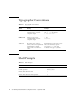
Typographic Conventions TABLE P-1 Typographic Conventions Typeface or Symbol Meaning Examples AaBbCc123 The names of commands, files, and directories; on-screen computer output. Edit your .login file. Use ls -a to list all files. % You have mail. AaBbCc123 What you type, when contrasted with on-screen computer output. % su Password: AaBbCc123 Book titles, new words or terms, words to be emphasized. Command-line variable; replace with a real name or value. Read Chapter 6 in the User’s Guide.
Related Documentation TABLE P-3 Related Documentation Title Part Number Sun StorEdge A3000 Controller Module Guide 805-4980-xx Sun StorEdge A3500 Task Map 805-4982-xx Sun Documentation on the Web The docs.sun.comsm web site enables you to access Sun technical documentation on the Web. You can browse the docs.sun.com archive or search for a specific book title or subject at: http://docs.sun.
viii Sun StorEdge A3500 Hardware Configuration Guide • September 1998
CHAPTER 1 Host Connections This chapter contains configurations for one or two Sun StorEdge A3000 controller modules connected to one or more hosts. It also contains information about connecting power to an Ultra™ host system.
1.1 Configuration Guidelines Use the following guidelines for installing and cabling or reconfiguring your system. ■ Do not exceed a SCSI bus length of 25 meters. ■ Make sure that the last Sun StorEdge A3000 controller module in any daisy chain has a total of two terminators, one in each SCSI OUT port. ■ If you are adding a controller module to an already existing configuration, halt all activity on the SCSI bus before removing any SCSI cables.
1.2 Supported Host Configurations The examples that follow show the cable connections for configurations that are supported by Sun Microsystems™. 1.2.
1.2.2 Daisy Chain You can daisy chain controller modules in the same or separate cabinets. SCSI cables FIGURE 1-2 Differential SCSI terminators Two Sun StorEdge A3000 Controller Modules Daisy Chained to One Host Note – The SCSI cables between the two controller modules are crossed to prevent the SCSI IDs for the controllers from conflicting.
1.2.
1.2.4 Multi-Initiator FIGURE 1-4 Two-Node Multi-Initiator Configuration Note – For more detailed information regarding the two-node multi-initiator configuration, such as setting host SCSI IDs, refer to the SPARCcluster™ PDB™ documentation that is shipped with the host system.
1.3 Ultra 2 Host System—Power Connection Requirement You can connect a controller module to an Ultra 2 host system; however, you must connect the power cord of the Ultra 2 host to one of the AC power sequencers in the expansion cabinet that contains the controller module.
1. Gain access to the AC power sequencers. See the documentation that came with the expansion cabinet. 2. Route the power cable from the Ultra 2 host under the expansion cabinet frame on the same side as the power sequencer. 3. Plug the power cord from the Ultra 2 host into the top power connector of either power sequencer (FIGURE 1-5). The power connectors are located on the other side of the power sequencer from the main switch. 4. Reassemble the expansion cabinet.
CHAPTER 2 StorEdge A3500 Configurations This chapter contains information about setting up the following configurations: ■ ■ ■ ■ One controller module with two StorEdge D1000 disk arrays (1x2) One controller module with five StorEdge D1000 disk arrays (1x5) Two controller modules with seven StorEdge D1000 disk arrays (2x7) Three controller modules with fifteen StorEdge D1000 disk arrays (3x15) The chapter is divided into the following sections: ■ StorEdge D1000 Disk Array Settings—page 2-2 ■ 1x2 Config
2.
2.1.1 1x2 Configuration 2.1.1.1 Option Switch Both disk arrays have split busses. Their option switches should be set as shown in FIGURE 2-2. 5 4 3 FIGURE 2-2 2 1 1x2 Option Switch Settings for StorEdge D1000 Disk Array This will cause the disk drives in the StorEdge D1000 disk arrays to be numbered as shown in FIGURE 2-3 and FIGURE 2-4.
2.1.1.2 Module ID Switch Ensure that the module IDs for the StorEdge D1000 disk arrays are set according to . 1x2 Module ID Switch Settings Disk array number Module ID setting 2 (Top) 2 1 (Bottom) 1 Note – Since the top and bottom disk arrays are split between one controller module, the Module IDs will overlap. This may result in error messages while the host system is booting. The ASC/ASCQ codes for this error is 98/01 and the Sense Key is 6.
2.1.2 1x5 Configuration 2.1.2.1 Option Switch All StorEdge D1000 disk arrays in this configuration should have their option switches set as shown in FIGURE 2-5. 5 4 3 FIGURE 2-5 2 1 1x5 Option Switch Settings for StorEdge D1000 Disk Array This will cause the disk drives in the StorEdge D1000 disk arrays to be numbered as shown in FIGURE 2-6 and FIGURE 2-7.
2.1.2.2 Module ID Switch Ensure that the module IDs for the StorEdge D1000 disk arrays are set according to TABLE 2-1. TABLE 2-1 2.1.2.3 1x5 Module ID Switch Settings Disk array number Module ID setting 5 (Top) 5 4 4 3 3 2 2 1 (Bottom) 1 SCSI Jumper Cables and Terminators All disk arrays in this configuration should have SCSI jumper cables between the middle SCSI connectors (IN/OUT-1 and IN/OUT-2) and a differential SCSI terminator in the far right SCSI connector (IN/OUT-2).
2.1.3 2x7 Configuration 2.1.3.1 Option Switch The disk drives in each of the top four disk arrays in FIGURE 2-17 are on a single bus and should be set as described in Section 2.1.2.1 “Option Switch” on page 2-5. The bottom three disk arrays have split busses. Their option switches should be set as shown in FIGURE 2-8.
2.1.3.2 Module ID Switch Ensure that the module IDs for the StorEdge D1000 disk arrays are set according to TABLE 2-2. TABLE 2-2 2x7 Module ID Switch Settings Disk array number Module ID setting 7 (Top) 5 6 4 5 5 4 4 3 3 2 2 1 (Bottom) 1 Facing the front of the expansion cabinet: ■ controller module A controls the right side of disk arrays 1 through 3 and all of disk arrays 4 and 5. ■ controller module B controls the left side of disk arrays 1 through 3 and all of disk arrays 6 and 7.
2.1.4 3x15 Configuration 2.1.4.1 Option Switch All disk arrays are on a single bus and should be set as described in Section 2.1.2.1 “Option Switch” on page 2-5. 2.1.4.2 Module ID Switch Ensure that the module IDs for the StorEdge D1000 disk arrays are set according to TABLE 2-3 and TABLE 2-4.
In this configuration: 2.1.4.
2.2 1x2 Cabling The 1x2 can be configured with the controller module either on top of or below the two disk arrays. Both configurations are described in this section. 2.2.1 SCSI Cabling 2.2.1.1 Cable Lengths The following table shows the lengths of each SCSI cable connected to the drive connections on the controller module. TABLE 2-5 Controller Module A (1x2) SCSI Port Number Cable Length Part Number 1 .8m 530-1884-xx 2 .8m 530-1884-xx 3 .8m 530-1884-xx 4 .
2.2.1.
2.2.2 Power Connections Because the controller module must receive power after the disk arrays, connect the disk arrays to the first stage of the power sequencer and the controller module to the second. Two examples are shown below.
2.3 1x5 Cabling 2.3.1 SCSI Cabling 2.3.1.1 Cable Lengths The following table shows the lengths of each SCSI cable connected to the drive connections on the controller module. TABLE 2-6 Controller Module A (1x5) SCSI Port Number Cable Length Part Number 1 2m 530-1885-xx 2 2m 530-1885-xx 3 2m 530-1885-xx 4 2m 530-1885-xx 5 2m 530-1885-xx The inboard IN/OUT connectors on each of the disk arrays are connected together using a 0.2m SCSI jumper cable, part number 530-1883-xx.
2.3.1.
2.3.
2.4 2x7 Cabling 2.4.1 SCSI Cabling 2.4.1.1 Cable Lengths The following tables show the lengths of each SCSI cable connected to the drive connections on the respective controller modules. TABLE 2-7 Controller Module A (2x7) SCSI Port Number Cable Length Part Number 1 .8m 530-1884-xx 2 .8m 530-1884-xx 3 .8m 530-1884-xx 4 2m 530-1885-xx 5 2m 530-1885-xx TABLE 2-8 Controller Module B (2x7) SCSI Port Number Cable Length Part Number 1 2m 530-1885-xx 2 .8m 530-1884-xx 3 .
2.4.1.
2.4.
2.5 3x15 Cabling This section contains information about SCSI and power connections for three StorEdge A3000 controller modules and fifteen StorEdge D1000 disk arrays in two StorEdge expansion cabinets. Caution – The components in the expansion cabinets are configured as a single unit. Make sure that the serial numbers on each expansion cabinet match.
2.5.1 SCSI Cabling 2.5.1.1 Cable Lengths The following tables show the lengths of each SCSI cable connected to the drive connections on the respective controller modules. TABLE 2-9 Controller Module A (3x15) SCSI Port Number Cable Length Part Number 1 .8m 530-1884-xx 2 .8m 530-1884-xx 3 4m 530-2352-xx 4 4m 530-2352-xx 5 4m 530-2352-xx TABLE 2-10 Controller Module B (3x15) SCSI Port Number Cable Length Part Number 1 .8m 530-1884-xx 2 .
The outboard IN/OUT-2 connector on each disk array is terminated with a differential SCSI terminator, part number 150-1890-xx. 2.5.1.
2.5.1.
2.5.1.
2.5.2 Power Connections 2.5.2.1 Power Sequencer Interconnections The front and rear power sequencers in the 2x7 cabinet and the 1x8 cabinet must be interconnected. Make sure an interconnect cable (part number 530-2235-xx) is connected between the OUT on the front sequencer in 2x7 cabinet and the IN on the front sequencer in 1x8 cabinet (FIGURE 2-22). Make sure that the rear sequencers are likewise connected. FIGURE 2-22 2.5.
2x7 Phase A FIGURE 2-23 2x7 1x8 Phase B Power Connections to Avoid (Different Phases) 1x8 Same phase AC FIGURE 2-24 2.5.4 Power Connections to Avoid (Same Phase) Power Connections The power connections for 2x7 cabinet are the same as those in the standard 2x7 expansion cabinet (FIGURE 2-18).
The power connections for the 1x8 cabinet are shown in FIGURE 2-25.
2-28 Sun StorEdge A3500 Hardware Configuration Guide • September 1998