
FC Dual GbE HBA, Emulex Installation Guide
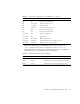
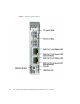
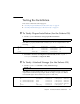
Table Of Contents
- Sun StorageTek™ Dual 4 Gb FC Dual GbE HBA, Emulex Installation Guide
- Contents
- Declaration of Conformity
- Safety Agency Compliance Statements
- Safety Precautions
- Conformité aux normes de sécurité
- Mesures de sécurité
- Symboles
- Modification du matériel
- Positionnement d’un produit Sun
- Niveau de pression acoustique
- Conformité SELV
- Connexion du cordon d’alimentation
- Mise en garde relative aux batteries
- Couvercle de l'unité
- Mise en garde relative au système en rack
- Avis de conformité des appareils laser
- Périphériques CD et DVD
- Einhaltung sicherheitsbehördlicher Vorschriften
- Normativas de seguridad
- Medidas de seguridad
- Símbolos
- Modificaciones en el equipo
- Colocación de un producto Sun
- Nivel de ruido
- Cumplimiento de la normativa para instalaciones SELV
- Conexión del cable de alimentación
- Advertencia sobre las baterías
- Cubierta de la unidad del sistema
- Advertencia sobre el sistema en bastidor
- Aviso de cumplimiento de la normativa para la utilización de láser
- Dispositivos de CD y DVD
- Nordic Lithium Battery Cautions
- Nordic Power Distribution Cautions
- Nordic Grounded Socket Cautions
- Regulatory Compliance Statements
- Preface
- HBA Overview
- Hardware Installation and Removal
- HBA Software Installation
- Known Issues
- Cannot Detect the HBA on the Sun Blade T6300 System (6680542)
- The PEM Might Not Come Online on a Sun Blade T6300 or T6320 System (6683536)
- Cannot Detect the HBA Through the BIOS on the Sun Blade X8450 System (6704510)
- Cannot Verify the FCode Version of the HBA on the Sun Blade T6300 and T6320 Systems (6686545)

Chapter 2 Hardware Installation and Removal 15
6. Observe the LEDs status for the Ethernet connection as shown in TABLE 2-5.
TABLE 2-5 summarizes LED indicator combinations. Refer to FIGURE 2-3 to
determine the location of the LEDs. Each Ethernet port has a corresponding set of
LEDs that provide a visual indication of the operating state.
Off On POST failure (failed board)
Off Slow blink Wake-up failure monitor
Off Fast blink Failure in POST
Off Flashing POST processing in progress
On Off Failure while functioning
On On Failure while functioning
Slow blink Off Normal - link down
Slow blink On Not defined
Slow blink Slow blink Offline for download
Slow blink Fast blink Restricted offline mode (waiting for restart)
Slow blink Flashing Restricted offline mode, test active
TABLE 2-5 Ethernet LED Indicator Status Definitions
Green LED Green/Yellow LED State
Blinks Off 10-Mb link rate - Normal operating state, link up
Blinks Green 100-Mb link rate - Normal operating state, link up
Blinks Yellow 1-Gb link rate - Normal operating state, link up
TABLE 2-4 Fibre channel LED Indicator Status Definitions (Continued)
Green LED Yellow LED State