
FC Dual GbE HBA, Emulex Installation Guide
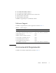
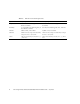
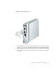
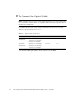
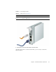
Table Of Contents
- Sun StorageTek™ Dual 4 Gb FC Dual GbE HBA, Emulex Installation Guide
- Contents
- Declaration of Conformity
- Safety Agency Compliance Statements
- Safety Precautions
- Conformité aux normes de sécurité
- Mesures de sécurité
- Symboles
- Modification du matériel
- Positionnement d’un produit Sun
- Niveau de pression acoustique
- Conformité SELV
- Connexion du cordon d’alimentation
- Mise en garde relative aux batteries
- Couvercle de l'unité
- Mise en garde relative au système en rack
- Avis de conformité des appareils laser
- Périphériques CD et DVD
- Einhaltung sicherheitsbehördlicher Vorschriften
- Normativas de seguridad
- Medidas de seguridad
- Símbolos
- Modificaciones en el equipo
- Colocación de un producto Sun
- Nivel de ruido
- Cumplimiento de la normativa para instalaciones SELV
- Conexión del cable de alimentación
- Advertencia sobre las baterías
- Cubierta de la unidad del sistema
- Advertencia sobre el sistema en bastidor
- Aviso de cumplimiento de la normativa para la utilización de láser
- Dispositivos de CD y DVD
- Nordic Lithium Battery Cautions
- Nordic Power Distribution Cautions
- Nordic Grounded Socket Cautions
- Regulatory Compliance Statements
- Preface
- HBA Overview
- Hardware Installation and Removal
- HBA Software Installation
- Known Issues
- Cannot Detect the HBA on the Sun Blade T6300 System (6680542)
- The PEM Might Not Come Online on a Sun Blade T6300 or T6320 System (6683536)
- Cannot Detect the HBA Through the BIOS on the Sun Blade X8450 System (6704510)
- Cannot Verify the FCode Version of the HBA on the Sun Blade T6300 and T6320 Systems (6686545)

14 Sun StorageTek Dual 4 Gb FC Dual GbE HBA, Emulex Installation Guide • July 2008
▼ To Connect the Ethernet Cable
Use high-quality Ethernet cable, category 5e or category 6, that adheres to the
specifications in
TABLE 2-3.
1. Connect the ethernet cable to RJ-45 connectors on the HBA (see
FIGURE 2-2).
2. Connect the other end of the cable to the Ethernet device.
After the ethernet cable is connected to the HBA, you are ready to apply power to
the system. If power is already applied to the system, proceed to “Configuring the
HBA for Hot-Plug Operation” on page 18.
▼ To Apply Power
1. Verify that the HBA is securely installed in the system.
2. Verify that the correct fiber-optic cable is attached.
3. Verify that the correct ethernet cable is attached.
4. Refer to your system installation or service manual to determine how to power
on the system blade.
5. Observe the light-emitting diode (LED) status for the power-on self test (POST)
results as shown in
TABLE 2-4.
TABLE 2-4 summarizes LED indicator combinations. Refer to FIGURE 2-3 to
determine the location of the LEDs. Each FC port has a corresponding set of LEDs
that provide a visual indication of the operating state.
TABLE 2-3 Ethernet Cable Specifications
Ethernet Cable Maximum Length Connector
Cat5e UTP 100 meters 8P8C
Cat6 UTP 100 meters 8P8C
TABLE 2-4 Fibre channel LED Indicator Status Definitions
Green LED Yellow LED State
On 1 fast blink 1-Gb link rate - Normal operating state, link up
On 2 fast blinks 2-Gb link rate - Normal operating state, link up
On 3 fast blinks 4-Gb link rate - Normal operating state, link up
Off Off Wake-up failure (failed board)