
Network Router User Manual

System Upgrade Procedure 3
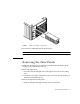
1. Disconnect all cables from the boards.
Squeeze the locking tabs on the sides of the connector body, or loosen any retaining
screws (if provided), and pull the connectors out.
Note – Label all cables for reconnection.
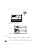
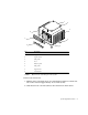
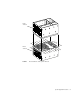
2. With wrist strap on, insert a screwdriver in the notch at the top of the SCSI tray to
pull out the tray and separate it from the rear slip connector (
FIGURE 3).
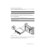
3. Remove all boards and power supplies from the front of the system and place
them on a padded ESD mat.
Refer to your system manual for the detailed procedure.
Note – Label each board with its respective slot number, so that each board can be
replaced in the correct slot.
FIGURE 3 SCSI Tray
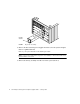
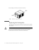
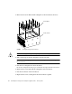
4. Loosen the two captive screws securing the keyswitch assembly to the system and
gently pull the keyswitch from the enclosure (
FIGURE 4).
Notch