Sun™ Datacenter Switch 3456 Service Manual Sun Microsystems, Inc. www.sun.com Part No. 820-4733-10 August 2008, Revision A Submit comments about this document at: http://www.sun.
Copyright 2008 Sun Microsystems, Inc., 4150 Network Circle, Santa Clara, California 95054, U.S.A. All rights reserved. Sun Microsystems, Inc. has intellectual property rights relating to technology embodied in the product that is described in this document. In particular, and without limitation, these intellectual property rights may include one or more of the U.S. patents listed at http://www.sun.com/patents and one or more additional patents or pending patent applications in the U.S.
Contents Preface 1. 2. vii Sun Datacenter Switch 3456 Overview 1.1 Switch Chassis 1.2 Power Supplies 1.3 Fan Units 1.4 Chassis Management Controllers 1.5 Fabric Cards 1.6 Line Cards 1–1 1–2 1–3 2.2 1–6 Filler Panels 2–1 2–1 ▼ Removing the Filler Panel ▼ Installing the Filler Panel Midplane Connector Pins 2.2.1 1–4 1–5 Chassis Service Procedures 2.
▼ 2.3 2.4 Inserting Pins Cable Management Hardware Removing Cable Plates ▼ Installing Cable Plates 16 ▼ Removing Cable Trees 17 ▼ Installing Cable Trees ▼ Removing Cable Trays ▼ Installing Cable Trays InfiniBand Cables 20 20 2–21 Cable Cautions 2–21 Removing Cables From the Sun Datacenter Switch 3456 ▼ Attaching Cables to the Sun Datacenter Switch 3456 3–1 3.1 Troubleshooting Power Supplies 3.2 Powering Off Power Supplies 3.3 Removing Power Supplies 3.
.1 Troubleshooting CMCs 5.2 Powering Off CMCs 5.3 Removing CMCs ▼ 5.4 5.5 6. 5–3 3 5–4 Installing a CMC Powering On CMCs 4 5–6 Fabric Card Service Procedures 6–1 6.1 Fabric Card Considerations 6.2 Troubleshooting Fabric Cards 6.3 Inspecting Fabric Cards Inspecting the Fabric Card iTRAC Connectors ▼ Inspecting the Fans ▼ Inspecting the Retainers 6.5 Removing Fabric Cards ▼ 5 6–6 6–7 Removing a Fabric Card Installing Fabric Cards 3 5 Powering Off Fabric Cards 6.
7.4 Powering Off Line Cards 7.5 Removing Line Cards ▼ 7.6 7.
Preface This service manual provides service procedures for the Sun Datacenter Switch 3456. This document is written for service personnel and users who have advanced knowledge and experience managing an InfiniBand network. Using UNIX Commands This document might not contain information about basic UNIX® commands and procedures such as shutting down the system, booting the system, and configuring devices.
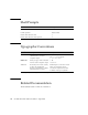
Shell Prompts Shell Prompt C shell machine-name% C shell superuser machine-name# Bourne shell and Korn shell $ Bourne shell and Korn shell superuser # Typographic Conventions Typeface* Meaning Examples AaBbCc123 The names of commands, files, and directories; on-screen computer output Edit your.login file. Use ls -a to list all files. % You have mail.
http://docs.sun.com/app/docs/prod/switch.
Sun Datacenter Switch 3456 Service Manual, part number 820-4733-10.
CHAPTER 1 Sun Datacenter Switch 3456 Overview This chapter provides a visual overview of the Sun Datacenter Switch 3456. Topics include: 1.1 ■ Section 1.1 “Switch Chassis” on page 1-1 ■ Section 1.2 “Power Supplies” on page 1-2 ■ Section 1.3 “Fan Units” on page 1-3 ■ Section 1.4 “Chassis Management Controllers” on page 1-4 ■ Section 1.5 “Fabric Cards” on page 1-5 ■ Section 1.6 “Line Cards” on page 1-6 Switch Chassis FIGURE 1-1 describes the various parts of the switch chassis.
FIGURE 1-1 Parts of the Switch Chassis 4 1 5 2 6 3 7 8 9 10 Figure Legend 1.2 1 Fabric cards (18) 6 Line cards (24) 2 Power supplies (16) 7 Cable trays (24) 3 Cable plates (left) 8 Cable tree (left) 4 Cable plates (right) 9 Chassis 5 Cable tree (right) 10 CMCs (2) Power Supplies FIGURE 1-2 describes the various parts of the power supplies.
FIGURE 1-2 Parts of the Power Supplies 1 2 3 4 5 Figure Legend 1.3 1 Power Distribution Board connector 2 Power cord connector 3 Status LEDs 4 Fan 5 Release lever Fan Units FIGURE 1-3 describes the various parts of the fan units.
FIGURE 1-3 Parts of the Fan Units 1 2 3 Figure Legend 1.4 1 Fabric card connector 2 Thumbscrews 3 Status LED Chassis Management Controllers FIGURE 1-4 describes the various parts of the chassis management controllers (CMCs).
FIGURE 1-4 Parts of the CMCs 1 2 3 4 Figure Legend 1 Release levers 2 Network management ports 3 Serial management ports 4 Status LEDs TABLE 1-1 lists the IPMB addresses for the CMCs. TABLE 1-1 Component 1.5 IPMB Addresses for the CMCs IPMB Address CMC0 10 CMC1 12 Fabric Cards FIGURE 1-5 describes the various parts of the fabric cards.
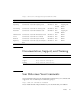
FIGURE 1-5 Parts of the Fabric Cards 2 1 3 4 Figure Legend 1 iTRAC connectors 2 Retainers 3 Fans 4 Status LEDs TABLE 1-2 lists the IPMB addresses for the fabric cards. TABLE 1-2 Fabric card IPMB address 1.6 IPMB Addresses for Fabric Cards FC0 FC1 FC2 FC3 FC4 FC5 FC6 FC7 FC8 FC9 FC10 FC11 FC12 FC13 FC14 FC15 FC16 FC17 b2 b4 b6 b8 ba bc be c0 c2 c4 c6 c8 Line Cards FIGURE 1-6 describes the various parts of the line cards.
FIGURE 1-6 Parts of the Line Cards 3 1 4 2 5 Figure Legend 1 Status LEDs 2 Link LEDs 3 iTRAC connectors 4 iPASS connectors 5 Retainers TABLE 1-3 lists the IPMB addresses for the line cards.
1-8 Sun Datacenter Switch 3456 Service Manual • August 2008
CHAPTER 2 Chassis Service Procedures This chapter describes procedures performed on the Sun Datacenter Switch 3456 chassis. Topic include: 2.1 ■ Section 2.1 “Filler Panels” on page 2-1 ■ Section 2.2 “Midplane Connector Pins” on page 2-6 ■ Section 2.3 “Cable Management Hardware” on page 2-16 Filler Panels ▼ Removing the Filler Panel 1. Grasp the locking levers at each end of the filler panel. See FIGURE 2-1.
FIGURE 2-1 Turning Filler Panel Lock Levers 2. Turn the levers counter-clockwise to the unlock position. See FIGURE 2-1. 3. Lift the filler panel away from the chassis by the handles. See FIGURE 2-2.
FIGURE 2-2 Removing the Filler Panel 4. Repeat from Step 1 for all remaining filler panels. ▼ Installing the Filler Panel After you remove fabric cards and line cards, you must install filler panels into the vacant slots to maintain proper airflow and thermal management. 1. Grasp the handles at each end of the filler panel and lift the panel to the vacant slot. 2. Turn the levers counter-clockwise to the unlock position. See FIGURE 2-3.
FIGURE 2-3 Turning Filler Panel Lock Levers Counter-Clockwise 3. Slide the filler panel into the chassis until it stops. See FIGURE 2-4.
4. Turn the levers clockwise to the lock position. See FIGURE 2-5. FIGURE 2-5 Turning Filler Panel Lock Levers Clockwise 5. Repeat from Step 1 for any remaining vacant slots. 2.2 Midplane Connector Pins Caution – All midplane connector pin operations require the Sun Datacenter Switch 3456 to be fully powered off. 2.2.
To repair or replace a pin, you need the following tools: ■ Molex pin replacement tool ■ Replacement pins (extracted from a spare iTRAC connector) ■ Head-mounted magnifier ■ Flashlight Note – Another person to assist you can make the task much easier. ▼ Inspecting the Pins on the Rear Side of the Midplane Note – This procedure assumes that a fabric card has been removed from the chassis. The primary tool used to check the midplane pins is the pin gauge block.
FIGURE 2-6 Fabric Card Connector Nomenclature The connector number is located above each connector and is unique. For example, the upper-left connector number is FC-R23-F0. The lower-right connector number is FC-R0-F17. The connector number is decoded as follows: ■ FC – Fabric card ■ Ra – Row a, where a is 0 through 23 ■ Fb – Frame b, where b is 0 through 17 The origin of this coordinate system is the lower-left corner, FC-R0-F0. In FIGURE 2-6, the connector identified is FC-R13-F15. 3.
5. Using the magnifying glass and the flashlight positioned above you, look at the individual pins of the connector. Look at the pins straight on. See FIGURE 2-7. FIGURE 2-7 Inspecting the Pins (Fabric Card) 6. Look for any light reflection inconsistencies. A bent pin reflects light differently, either brighter or darker than the surrounding pins. Note – Do not look at the individual pins, rather look at all of the connector’s pins as a whole. A bent pin will be apparent. 7.
▼ Inspecting the Pins on the Front Side of the Midplane Note – This procedure assumes that a line card has been removed from the chassis. The primary tool used to check the midplane pins is the pin gauge block. This tool effortlessly slides over the straight pins of an iTRAC connector that is in good condition. If there is any resistance, a pin is bent and requires further examination. 1. Using the pin gauge block, gently insert it into the iTRAC connector at the left end of the open slot. 2.
FIGURE 2-8 Line Card Connector Nomenclature The connector number is located above each connector and is unique. For example, the lower-left connector number is LC-C17-L0. The upper-right connector number is LC-C0-L23. The connector number is decoded as follows: ■ LC – Line card ■ Cc – Column c, where c is 0 through 17 ■ Ld – Level d, where d is 0 through 23 The origin of this coordinate system is the lower right corner, LC-C0-L0. In FIGURE 2-8, the connector identified is LC-C14-L10. 3.
5. Using the magnifying glass and the flashlight positioned to the side of you, look at the individual pins of the connector. Look at the pins as straight on. See FIGURE 2-9. FIGURE 2-9 Inspecting the Pins (Line Card) 6. Look for any light reflection inconsistencies. A bent pin reflects light differently, either brighter or darker than the surrounding pins. Note – Do not look at the individual pins, rather look at all of the connector’s pins as a whole. A bent pin will be apparent. 7.
▼ Removing Pins Before you can attempt to straighten a bent pin, you must remove the pins surrounding the bent pin. See FIGURE 2-10. 1. Locate the bent pin. See FIGURE 2-10. FIGURE 2-10 Locating the Bent Pin and Surrounding Pins 2. Use the Molex tool to remove the pin (if any) above the bent pin. a. Slide the Molex tool completely over the pin. b. Activate the lock to grasp the pin. c. Press the trigger to pull the pin out. d. Push the ejector back in to release the pin and reset the tool. 3.
6. Repeat Step 2 to remove the pins to the left and right sides of the bent pin (if any). 7. Set these pins aside. The bent pin is now exposed. 8. Flip the Molex tool over and use the tube in attempt to straighten the pin. If the pin cannot be straightened satisfactorily, or might break if straightened, replace it. 9. Remove the pin following Step 2. 10. If the pin is too bent for the Molex tool, see “Removing a Pin With Needle-Nose Pliers” on page 2-14.
FIGURE 2-11 Using Pliers to Pull a Pin 4. In one motion, use both hands to pull the pin out of the connector. 5. Dispose of the pin. ▼ Inserting Pins When inserting pins, work from the top down. Repeat Step 1 through Step 5 for each pin that needs to be inserted. 1. Ready the Molex tool for a pin insertion. a. Press the trigger on the Molex tool to release the ejector. b. Slide a pin into the opening. A portion of the pin protrudes. c. Activate the lock to grasp the pin. 2.
4. Slowly press the ejector in until it stops. The pin is inserted. 5. Carefully deactivate the lock and withdraw the Molex tool from the connector. 2.3 Cable Management Hardware ▼ Removing Cable Plates 1. Remove the cables from the cable plates. See “Removing Cables From the Sun Datacenter Switch 3456” on page 2-22. 2. Starting on the right side of the Sun Datacenter Switch 3456 chassis, remove the cable plates. a. Using an Allen wrench, remove the four M5 x 1.5 screws that secure the upper cable plate.
FIGURE 2-12 Cable Plate Locations Note – The support rib for the plate is on the underside and visible from the front of the switch chassis. From the back of the switch, the plates appear smooth. b. Tighten the screws securely. c. Repeat from Step a for the next higher cable plate and continue until all six cable plates are installed. 2. Repeat Step 1 for the left side of the switch. ▼ Removing Cable Trees Note – Two people are required to remove the cable trees.
2. Start on the front right corner of the Sun Datacenter Switch 3456 chassis. a. Remove all screws from the front of the cable tree. b. Remove all but the upper two screws from the right side of the cable tree. c. While a helper lifts the weight of the cable tree, remove the two remaining screws from the right of the cable tree. d. Lift the cable tree away from the chassis. 3. Repeat Step 2 for the cable tree on the front left corner of the switch chassis.
FIGURE 2-13 Cable Tree Placement 2. Set the cable trees upright at their respective corners of the switch chassis. 3. Starting on the front right corner of the chassis, lift the cable tree into position. Have a helper assist in aligning the cable tree mounting screw holes with those in the chassis. 4. While holding the cable tree in position, have a helper install the mounting screws. a. Using a Allen wrench, install the first M5x1.5 screw into the top hole on the right side of the chassis.
▼ Removing Cable Trays 1. Remove the cables from the line card where the cable tray is to be removed. See “Removing Cables From the Sun Datacenter Switch 3456” on page 2-22. 2. Lift on the front of the cable tray and begin to pull out. Note – Once the tray is free of the guides at the back end, it no longer has support and will fall. Anticipate this behavior. 3. Support the back end of the cable tray, and continue to pull the tray out and away from the cable trees. ▼ Installing Cable Trays 1.
FIGURE 2-14 Installing Cable Trays Note – Install cable trays only as they are needed. If all cable trays are installed before the switch is cabled, their presence make cabling extremely difficult. 2.4 InfiniBand Cables 2.4.1 Cable Cautions Caution – Do not allow any IB cable to bend through a less than 5 inch (127 mm) radius. Tight bends can break the cable internally. Caution – Do not use zip ties to bundle or support IB cables. The sharp edges of the ties can break the cables internally.
Caution – Do not allow any IB cable to experience extreme tension. Do not pull on an IB cable or allow it to drag. Unroll an IB cable for its length. Pulling on an IB cable can break the cables internally. Caution – Do not twist an IB cable more than 1 revolution for its entire length. Twisting an IB cable can break the cable internally. Caution – Do not route IB cables where they might be stepped upon or experience rolling loads. Such a crushing effect can break the cable internally.
a. Unthread the cable out of the side branch of the cable tree, and off of the cable plate. b. Gently lower the cable to the floor. ■ If you are disconnecting cables for a line card replacement: c. Gently lower the cable so that is it hanging from the side branch. Caution – Do not allow the cable to drop or strike the floor. Jerking, bending, pulling on, or dropping the cable can damage the cable. See Section 2.4.1 “Cable Cautions” on page 2-21. 6. Repeat from Step 1 for the cable at 12A.
FIGURE 2-15 Threading the Cable Through the Cable Tree Caution – Do not force a bend radius of less than 5 inches (127 mm). Any bend tighter than this damages the inner fibers of the cable, rendering it useless. 4. Plug the first cable into the connector at 23A. See FIGURE 2-16.
FIGURE 2-16 Plugging in an IB Cable a. Visually inspect the cable connector to see whether the shell is not bent and is parallel to the inner boards. If the shell is bent or damaged, get a different cable. b. Ensure that the retraction strap is forward. c. Orient the cable connector to horizontal. Ensure that the upper shell just touches the underside of the top of the connector on the line card. See FIGURE 2-17. FIGURE 2-17 Checking the IB Cable Connector d. Slowly move the connector in.
■ If the connector stops or binds with about 2 mm still to go, back out and repeat from Step c. e. Continue to push the connector in until the hooks catch onto the top of the connector on the line card. 5. Repeat from Step 2 for the second cable connecting to connector 23B. 6. Repeat from Step 2 moving to the left for cables connecting to connector 22A, 22B, 21A, and so on to 12B. 7. Repeat from Step 2 moving to the right for cables connecting to connector 0A, 0B, 1A, and so on to 11B.
2-26 Sun Datacenter Switch 3456 Service Manual • August 2008
CHAPTER 3 Power Supply Service Procedures This chapter describes procedures for servicing the switch power supplies. Topics include: ■ Section 3.1 “Troubleshooting Power Supplies” on page 3-2 ■ Section 3.2 “Powering Off Power Supplies” on page 3-2 ■ Section 3.3 “Removing Power Supplies” on page 3-3 ■ Section 3.4 “Installing Power Supplies” on page 3-5 ■ Section 3.5 “Powering On Power Supplies” on page 3-7 Commands described in this chapter are executed at the management console.
3.1 Troubleshooting Power Supplies The status LEDs on the power supplies can help you determine the problem with the power supplies. See TABLE 3-1. TABLE 3-1 Glyph Power Supply Status LEDs Name Color State and Meaning Active Green On – Power supply enabled, 12 VDC is supplied. Off – Power supply disabled, 12 VDC is not supplied. Flashing – No function.
3.3 Removing Power Supplies ▼ Removing a Power Supply 1. Determine which power supply is to be removed. 2. Use the disablepsu command to bring the power supply to a standby state. 3. At the power supply, remove the power cord. See FIGURE 3-2. FIGURE 3-1 Removing the Power Cord The power supply is completely powered off. 4. Swing the release lever of the power supply out and to the right. See FIGURE 3-2.
FIGURE 3-2 Releasing the Power Supply 5. Pull the handle of the power supply to remove it from the chassis. See FIGURE 3-3. FIGURE 3-3 Removing the Power Supply 6. Set the power supply aside.
3.4 Installing Power Supplies ▼ Installing a Power Supply 1. Unwrap the replacement power supply from its antistatic packaging. 2. Swing open the release lever. 3. Orient the power supply with the handle on the left and the receptacle on the right. 4. Slide the power supply into the open slot, pushing the power supply in until the release lever moves. See FIGURE 3-4. FIGURE 3-4 Installing the Power Supply 5. Swing the release lever to the left to secure the power supply into the chassis. See FIGURE 3-5.
FIGURE 3-5 Securing the Power Supply 6. Reconnect the power cord. See FIGURE 3-2.
FIGURE 3-6 Attaching the Power Cord The Connected LED lights to indicate the power supply is connected to facility power. 7. Use the enablepsu command to bring the power supply to a fully powered state. 8. Verify the power supply’s operation with the showpresent and psustatus commands. 3.5 Powering On Power Supplies When facility power is applied to a power supply, it enters a standby state.
Use the enablepsu command to bring the power supply from a standby state to full power. For example, to bring power supply 0 (PSU0) to full power: # enablepsu 0 Using psu i2c addr 0x5d Turning on 12V ...
CHAPTER 4 Fan Service Procedures This chapter describes procedures for servicing the fans on the fabric cards. Topics include: ■ Section 4.1 “Troubleshooting Fans” on page 4-1 ■ Section 4.2 “Removing Fans” on page 4-1 ■ Section 4.3 “Installing Fans” on page 4-2 Commands described in this chapter are executed at the management console. See the Sun Datacenter Switch 3456 Administration Guide for more information about these commands. 4.
1. Determine which fan is to be removed. If a fan has failed, its LED flashes. 2. Loosen the two captive thumbscrews on either side of the fan. See FIGURE 4-1. FIGURE 4-1 Removing the Fan 3. Pull the fan straight out. See FIGURE 4-1. 4. Set the fan aside. 4.3 Installing Fans Note – Fans are hot-swappable and can be inserted into live fabric cards.
▼ Installing a Fan 1. Unwrap the replacement fan from its antistatic packaging. 2. Orient the fan over the opening in the fabric card with the LED at the bottom. 3. Slide the fan into the fabric card until the fan stops. See FIGURE 4-2. FIGURE 4-2 Installing the Fan The fan might immediately power on. 4. Tighten the captive thumbscrews to secure the fan in the fabric card. See FIGURE 4-2. 5. Use the checkfans and getfans commands to verify the fan’s operation.
4-4 Sun Datacenter Switch 3456 Service Manual • August 2008
CHAPTER 5 Chassis Management Controller Service Procedures This chapter describes procedures for servicing the CMCs. Topics include: ■ Section 5.1 “Troubleshooting CMCs” on page 5-2 ■ Section 5.2 “Powering Off CMCs” on page 5-2 ■ Section 5.3 “Removing CMCs” on page 5-3 ■ Section 5.4 “Installing CMCs” on page 5-4 ■ Section 5.5 “Powering On CMCs” on page 5-6 Commands described in this chapter are executed at the management console.
5.1 Troubleshooting CMCs The chassis management controllers (CMCs) have several status LEDs that can provide some troubleshooting assistance. See TABLE 5-1. TABLE 5-1 Glyph CMC Status LEDs Name Color State and Meaning Attention Amber On – A fault has been detected. Off – Normal operation. Flashing – A critical error has happened. Ready-to-Remove Blue On – CMC is ready to be removed. Off – Do not remove the CMC. Flashing – No function. OK Green On – CMC is operating normally.
For example, to deactivate CMC0 (10h): # clia deactivate 10 0 Pigeon Point Shelf Manager Command Line Interpreter Command issued via IPMB, status = 0 (0x0) Command executed successfully # Instead of deactivating a CMC, you can use the clia switchover command. The clia switchover command transfers control of the Sun Datacenter Switch 3456 from one CMC to the other. For example: # clia switchover # Note – You can use the clia switchover command on either the active or the inactive CMC with the same results.
FIGURE 5-1 Removing the CMC 5. Slowly pull the CMC from the chassis. See FIGURE 5-1. 6. Set the CMC aside. 5.4 Installing CMCs ▼ Installing a CMC 1. Remove the replacement CMC from its antistatic packaging. 2. Squeeze the latches on the release levers and swing the levers outward. 3. Set the back of the CMC onto the rails inside the chassis.
4. Carefully slide the CMC into the chassis until the release levers move. See FIGURE 5-2. FIGURE 5-2 Installing and Securing the CMC 5. Swing the release levers inward to secure the CMC into the chassis. See FIGURE 5-2. 6. Reconnect the cables you removed previously to the front panel. 7. Configure the new CMC. See the Sun Datacenter Switch 3456 Installation Guide or Sun Datacenter Switch 3456 Administration Guide. 8.
5.5 Powering On CMCs When a CMC is plugged into a powered chassis, the CMC is powered on by the presence of standby voltage. Although the CMC is on, it might be inactive. A CMC can be made active, using the clia switchover command. For example: # clia switchover This Shelf Manager is now active, but is shutting down to trigger a switchover.
CHAPTER 6 Fabric Card Service Procedures This chapter describes procedures for servicing the fabric cards. Topics include: ■ Section 6.1 “Fabric Card Considerations” on page 6-1 ■ Section 6.2 “Troubleshooting Fabric Cards” on page 6-2 ■ Section 6.3 “Inspecting Fabric Cards” on page 6-3 ■ Section 6.4 “Powering Off Fabric Cards” on page 6-6 ■ Section 6.5 “Removing Fabric Cards” on page 6-7 ■ Section 6.6 “Installing Fabric Cards” on page 6-8 ■ Section 6.
6.2 Troubleshooting Fabric Cards The status LEDs on the fabric cards can help you determine the problem with the fabric cards. See TABLE 6-1. TABLE 6-1 Fabric Card Status LEDs Glyph Name Color State and Meaning Locator White On – No function. Off – Normal operation. Flashing – The fabric card is identifying itself. Ready-to-Remove Blue On – Fabric card has been disabled and is ready to be removed. Off – Do not remove Flashing – No function. Attention Amber On – Fault detected.
6.3 Inspecting Fabric Cards Caution – Inspect the replacement fabric card before removing the defective fabric card from the chassis. This way, you can make a quick exchange and not compromise the thermal management of the switch. ▼ Inspecting the Fabric Card iTRAC Connectors The iTRAC connectors on fabric cards are the receptacles for the midplane connector pins. These connectors are checked just as meticulously as the midplane connector pins.
FIGURE 6-1 Inspecting Fabric Card Connectors Note – Do not look at the individual holes, rather look at all of the connector’s holes as a group. A damaged or contaminated hole will be apparent. 4. Look for any closed over or contaminated holes. A closed-over or contaminated hole appears brighter than the surrounding holes. If you see any closed-over or contaminated holes, use the magnifying glass and pick to remove the contamination or open the closed-over hole.
6. Move your head slightly right to the next connector, and inspect its pins, repeating Step 4 and Step 5. 7. Continue in this manner for each connector until you reach the right side of the fabric card. ▼ Inspecting the Fans The fans of the fabric card are FRU components. The fans secure in position with two thumbscrews. 1. Ensure that each fan is seated properly in the fabric card. 2. Ensure that both thumbscrews are tight on each fan.
FIGURE 6-2 6.4 Retainer Design Powering Off Fabric Cards Powering off a fabric card is a two-stage process. First you must take the fabric card to a standby state, then you can power off the fabric card completely. The deactivate command powers down the fabric card to a standby state.
The disableboard command completely powers down (disable) a fabric card so that it can be removed from the chassis. For example, to disable fabric card 14: # disableboard fc 14 # 6.5 Removing Fabric Cards This procedure describes how to remove one fabric card as part of a replacement operation. ▼ Removing a Fabric Card Caution – Before beginning this procedure, have a fabric card filler panel or replacement fabric card prepared and standing by for immediate installation.
7. Rotate both retainer levers to the unlock position. 8. Grasp the handles at both ends of the fabric card and slowly pull it from the chassis. Stop when the fabric card is halfway out. 9. Improve your grip to support the weight of the fabric card. 10. Continue to pull the fabric card out. 11. Lift the fabric card out and away from the chassis. 12. Set the fabric card onto a flat horizontal work surface. 13. Immediately install replacement fabric card or filler panel into the vacant slot.
2. Unwrap the fabric card from its antistatic packaging. 3. Inspect the connectors, fans, and retainers. See: ■ “Inspecting the Fabric Card iTRAC Connectors” on page 6-3 ■ “Inspecting the Fans” on page 6-5 ■ “Inspecting the Retainers” on page 6-5 4. Place a fabric card on a work surface, with the retainers facing the two installers. 5. Using a 17 mm socket and ratchet, turn each retainer drive screw fully counter-clockwise until resistance is felt. 6.
14. Slowly rotate each retainer drive screw clockwise, until resistance is felt, then stop. 15. Simultaneously rotate the retainer drive screws clockwise, stopping at each half turn, to maintain synchronization. During this time, the retainer levers might have moved from the locked position. Move the levers back to the locked position and continue. 16. Continue synchronized rotation until greater resistance is felt, then stop. 17. Verify that the fabric card is properly seated in the slot. 18.
■ checkvoltages ■ checkswitches ■ showtemps More complex and verbose commands are available for verification. See the Sun Datacenter Switch 3456 Administration Guide and Sun Datacenter Switch 3456 Reference Manual for further information.
6-12 Sun Datacenter Switch 3456 Service Manual • August 2008
CHAPTER 7 Line Card Service Procedures This chapter describes procedures for servicing the line cards. Topics include: ■ Section 7.1 “Line Card Considerations” on page 7-1 ■ Section 7.2 “Troubleshooting Line Cards” on page 7-2 ■ Section 7.3 “Inspecting Line Cards” on page 7-3 ■ Section 7.4 “Powering Off Line Cards” on page 7-6 ■ Section 7.5 “Removing Line Cards” on page 7-7 ■ Section 7.6 “Installing Line Cards” on page 7-12 ■ Section 7.
You must inspect the front and back line card connectors, and retainers before installing the line card into the switch chassis. 7.2 Troubleshooting Line Cards The status LEDs on the line cards can help you determine the problems with the line cards. See TABLE 7-1. TABLE 7-1 Line Card Status LEDs Glyph Name Color State and Meaning Locator White On – No function. Off – Normal operation. Flashing – The line card is identifying itself.
7.3 Inspecting Line Cards Caution – Inspect the replacement line card before removing the defective line card from the chassis. This way, you can make a quick exchange and not compromise the thermal management of the switch. ▼ Inspecting the Line Card iTRAC Connectors The large iTRAC connectors on line cards are the receptacles for the midplane connector pins. These connectors are checked just as meticulously as the midplane connector pins.
FIGURE 7-1 Inspecting Line Card Connectors Note – Do not look at the individual holes, rather look at all of the connector’s holes as a group. A damaged or contaminated hole will be apparent. 4. Look for any closed over or contaminated holes. A closed-over or contaminated hole appears brighter than the surrounding holes. If you see any closed-over or contaminated holes, use the magnifying glass and pick to remove the contamination or open the closed-over hole.
6. Move your head slightly right to the next connector, and inspect its pins, repeating Step 4 and Step 5. 7. Continue in this manner for each connector until you reach the right side of the line card. ▼ Inspecting the Line Card iPASS Connectors The small iPASS connectors on the line card are for the InfiniBand cables. The design of these connectors is much simpler and more robust, so inspection is much easier. ● Check the small connectors for any debris, or cracked or bent fittings.
FIGURE 7-2 7.4 Retainer Design Powering Off Line Cards Powering off a line card is a two-stage process. First you must take the line card to a standby state, then you can power off the line card completely. The deactivate command powers down the line card to a standby state.
7.5 Removing Line Cards This procedure describes how to remove one line card as part of a replacement operation. ▼ Removing a Line Card Caution – Before beginning this procedure, have a line card filler panel or replacement line card prepared and standing by for immediate installation. A quick exchange is necessary to maintain chassis thermal management.
FIGURE 7-3 Unlocking Retainer Levers 9. Grasp the handles at both ends of the line card and slowly pull it from the chassis. Stop when the line card is halfway out. See FIGURE 7-4.
10. Improve your grip to support the weight of the line card. 11. Continue to pull the line card out. 12. Lift the line card out and away from the chassis. 13. Set the line card onto a flat horizontal work surface. 14. Immediately install replacement line card or filler panel into the vacant slot. Continue to “Installing a Line Card” on page 7-12, Step 8, or perform the following: a. Grasp the handles at each end of the filler panel and lift the panel to the vacant slot. b.
FIGURE 7-6 Installing the Filler Panel d. Turn the levers clockwise to the lock position. See FIGURE 7-7. FIGURE 7-7 Turning Filler Panel Lock Levers Clockwise 15. Retract and secure the antitilt bar.
7.6 Installing Line Cards This procedure describes how to install one line card as part of a replacement operation. If you are installing more than one line card, repeat the procedure for each line card. Alternatively, refer to the Sun Datacenter Switch 3456 Installation Guide. ▼ Installing a Line Card Installing the line card is a two-person task, as both people must work in a synchronized manner.
FIGURE 7-8 Turning Filler Panel Lock Levers b. Turn the levers counter-clockwise to the unlocked position. See FIGURE 7-8. c. Lift the filler panel away from the chassis by the handles. See FIGURE 7-9.
FIGURE 7-9 Removing the Filler Panel d. Set the filler panel aside. 8. Lift the line card from the work surface and orient it horizontally, with the link LEDs across the bottom. 9. Insert the line card into the chassis at the vacant slot. Ensure that the line card is square to the chassis and not skewed. Note – Once the line card is about halfway into the slot, it is no longer necessary to bear the weight of the line card. 10. Continue to slide the line card in, maintaining a squared orientation.
15. Simultaneously rotate the retainer drive screws clockwise, stopping at each half turn, to maintain synchronization. During this time, the retainer levers might have moved from the locked position. Move the levers back to the locked position and continue. 16. Continue synchronized rotation until greater resistance is felt, then stop. 17. Verify that the line card is properly seated in the slot. 18. Give each retainer drive screw a final turn to torque. 19. Retract and secure the antitilt bar. 20.
■ checkvoltages ■ checkswitches ■ showtemps More complex and verbose commands are available for verification. See the Sun Datacenter Switch 3456 Administration Guide and Sun Datacenter Switch 3456 Reference Manual for further information.
7-16 Sun Datacenter Switch 3456 Service Manual • August 2008
Index A activate command, 6-10, 7-15 attaching cables, 2-23 C cable plates installing, 2-16 removing, 2-16 trays installing, 2-20 removing, 2-20 trees installing, 2-18 removing, 2-17 cables attaching, 2-23 cautions, 2-21 removing, 2-22 cautions, 2-21 chassis parts front, 1-1 CMCs connectors, 1-4 installing, 5-4 IPMB addresses, 1-5 LEDs location, 1-4 status, 5-2 parts, 1-4 powering off, 5-2 on, 5-6 removing, 5-3 troubleshooting, 5-2 commands clia deactivate, 5-2 switchover, 5-3, 5-6 switch-specific activa
F fabric cards connectors, 1-5 inspecting, 6-3 fans, 6-5 iTRAC connectors, 6-3 retainers, 6-5 inspection tools, 6-3 installing, 6-8 IPMB addresses, 1-6 LEDs location, 1-5 status, 6-2 midplane connector nomenclature, 2-8 parts, 1-5 powering off, 6-6 on, 6-10 removing, 6-7 troubleshooting, 6-2 fans connectors, 1-3 installing, 4-3 LEDs location, 1-3 status, 4-1 parts, 1-3 removing, 4-1 troubleshooting, 4-1 filler panels installing, 2-3 removing, 2-1 I inserting pins, 2-15 inspecting fabric cards, 6-3 fans, 6-
power supplies, 3-2 midplane connector nomenclature, 2-11 parts, 1-6 powering off, 7-6 on, 7-15 removing, 7-7 troubleshooting, 7-2 on CMCs, 5-6 fabric cards, 6-10 line cards, 7-15 power supplies, 3-7 R M midplane connector nomenclature fabric cards, 2-8 line cards, 2-11 P parts chassis front, 1-1 CMCs, 1-4 fabric cards, 1-5 fans, 1-3 line cards, 1-6 power supplies, 1-2 pins gauge block, 2-7 inserting, 2-15 inspecting front, 2-10 rear, 2-7 removing, 2-13 with needlenose pliers, 2-14 power supplies connec
Index-4 Sun Datacenter Switch 3456 Service Manual • August 2008