Sun™ StorEdge™ FC-100 Hub Installation and Service Manual Formerly the Sun™ Enterprise Network Array™ Sun Microsystems, Inc. 901 San Antonio Road Palo Alto, CA 94303-4900 USA 650 960-1300 Fax 650 969-9131 Part No. 805-0315-12 September 1998, Revision A Send comments about this document to: docfeedback@sun.
Copyright 1998 Sun Microsystems, Inc. 901 San Antonio Road • Palo Alto, CA 94303 USA. All rights reserved. This product or document is protected by copyright and distributed under licenses restricting its use, copying, distribution, and decompilation. No part of this product or document may be reproduced in any form by any means without prior written authorization of Sun and its licensors, if any. Third-party software, including font technology, is copyrighted and licensed from Sun suppliers.
Regulatory Compliance Statements Your Sun product is marked to indicate its compliance class: • • • Federal Communications Commission (FCC) — USA Department of Communications (DOC) — Canada Voluntary Control Council for Interference (VCCI) — Japan Please read the appropriate section that corresponds to the marking on your Sun product before attempting to install the product. FCC Class A Notice This device complies with Part 15 of the FCC Rules. Operation is subject to the following two conditions: 1.
DOC Class A Notice - Avis DOC, Classe A This Class A digital apparatus meets all requirements of the Canadian Interference-Causing Equipment Regulations. Cet appareil numérique de la classe A respecte toutes les exigences du Règlement sur le matériel brouilleur du Canada. DOC Class B Notice - Avis DOC, Classe B This Class B digital apparatus meets all requirements of the Canadian Interference-Causing Equipment Regulations.
Safety Agency Compliance Statements Read this section before beginning any procedure. The following text provides safety precautions to follow when installing a Sun Microsystems product. Safety Precautions For your protection, observe the following safety precautions when setting up your equipment: • Follow all cautions and instructions marked on the equipment. • Ensure that the voltage and frequency of your power source match the voltage and frequency inscribed on the equipment’s electrical rating label.
! Caution – Do not operate Sun products without the top cover in place. Failure to take this precaution may result in personal injury and system damage. Achtung – Gefährliche Spannungen. Anweisungen befolgen, um Stromschläge und Verletzungen zu vermeiden. Laser Compliance Notice Sun products that use laser technology comply with Class 1 laser requirements. Ein – Setzt das System unter Wechselstrom.
Achtung – Nicht alle Netzkabel haben die gleichen Nennwerte. Herkömmliche, im Haushalt verwendete Verlängerungskabel besitzen keinen Überlastungsschutz und sind daher für Computersysteme nicht geeignet. Achtung – Ihr Sun-Gerät wird mit einem dreiadrigen Netzkabel für geerdete Netzsteckdosen geliefert. Um die Gefahr eines Stromschlags zu reduzieren, schließen Sie das Kabel nur an eine fachgerecht verlegte, geerdete Steckdose an.
Modification du matériel Ne pas apporter de modification mécanique ou électrique au matériel. Sun Microsystems n’est pas responsable de la conformité réglementaire d’un produit Sun qui a été modifié. L'avertissement suivant s'applique uniquement aux systèmes équipés d'un interrupteur VEILLEUSE: Attention : le commutateur d’alimentation de ce produit fonctionne comme un dispositif de mise en veille uniquement. C’est la prise d’alimentation qui sert à mettre le produit hors tension.
• No introduzca nunca objetos de ningún tipo a través de los orificios del equipo. Pueden haber voltajes peligrosos. Los objetos extraños conductores de la electricidad pueden producir cortocircuitos que provoquen un incendio, descargas eléctricas o daños en el equipo. Símbolos En este libro aparecen los siguientes símbolos: ! Precaución – Existe el riesgo de lesiones personales y daños al equipo. Siga las instrucciones. Precaución – Superficie caliente. Evite el contacto.
! Precaución – Es peligroso hacer funcionar los productos Sun sin la tapa superior colocada. El hecho de no tener en cuenta esta precaución puede ocasionar daños personales o perjudicar el funcionamiento del equipo. Aviso de cumplimiento con requisitos de láser Los productos Sun que utilizan la tecnología de láser cumplen con los requisitos de láser de Clase 1.
Declaration of Conformity Compliance ID: HUB 1063 Product Name: Sun StorEdge FC-100 Hub This product has been tested and complies with; EMC European Union-EC This equipment complies with the following requirements of the EMC Directive 89/336/EEC EN55022 / CISPR22 (1985) Class A EN50082-1 IEC801-2 (1991) 4 kV (Direct), 8 kV (Air) IEC801-3 (1984) 3 V/m IEC801-4 (1988) EN61000-3-2/IEC1000-3-2(1994) 1.0 kV Power Lines, 0.
xii Sun StorEdge FC-100 Hub Installation and Service Manual • September 1998
Contents Preface 1. 2. Product Description 1-1 1.1 Sun StorEdge FC-100 Hub 1.2 GBIC Installation 1-1 1-3 2-1 2.1 Inspecting the Hub 2.2 Rackmount Placement 2.3 Installing the Hub 2.4 3. xv 2-1 2-1 2-2 2.3.1 Tools You Will Need 2.3.2 Preparing the Cabinet 2.3.3 Installing the Mounting Tray in the Cabinet 2.3.4 Installing the Hub on the Mounting Tray 2.3.5 Installing GBICs and Fiber Optic Cables 2.3.6 Routing the Power Cord 2.3.7 Verifying the Configuration 2.3.
3.1 Installing a GBIC 3.2 Removing a GBIC 3.3 Removing a Hub A.
Preface The Sun StorEdge FC-100 Hub Installation and Service Manual provides information on installing and servicing the Sun™ StorEdge™ FC-100 Hub. These instructions are designed for an experienced system administrator or trained service provider. Using UNIX Commands This document does not contain information on basic UNIX® commands and procedures such as shutting down the system, booting the system, and configuring devices.
Typographic Conventions TABLE P-1 Typographic Conventions Typeface Meaning Examples AaBbCc123 The names of commands, files, and directories; on-screen computer output Edit your .login file. Use ls -a to list all files. % You have mail. AaBbCc123 What you type, when contrasted with on-screen computer output % su Password: AaBbCc123 Book titles, new words or terms, words to be emphasized Read Chapter 6 in the User’s Guide. These are called class options. You must be superuser to do this.
Related Documentation Refer to the Sun StorEdge A5000 Disk Array Installation and Documentation Guide, part number 805-1903-xx, for a list of related documentation Sun Documentation on the Web The docs.sun.comsm web site enables you to access Sun technical documentation on the Web. You can browse the docs.sun.com archive or search for a specific book title or subject at: http://docs.sun.
xviii Sun StorEdge FC-100 Hub Installation and Service Manual • September 1998
CHAPTER 1 Product Description This chapter describes the Sun StorEdge FC-100 Hub and Gigabit Interface Converters (GBICs). 1.1 Sun StorEdge FC-100 Hub The hub is a seven-port connection point for Fibre Channel Arbitrated Loops (FC-ALs). Ports are connected using GBICs. Each port receives serial data from a remote node and retransmits that data out the next port to the next node in the loop.
Data transfer within the hub is implemented in serial differential Positive Emitter Coupled Logic (PECL) AC coupled logic. Each port monitors the serial data input stream as well as the media converter connected to it. Initiators or targets on the loop represent individual nodes that are linked by the shared Fibre Channel loop. The positioning of the initiators or targets on the loop depends upon the requirements of your application. The front and rear of the hub are shown in FIGURE 1-1 and FIGURE 1-2.
1.2 GBIC The GBIC is compliant with Fibre Channel FC-PH-2 physical layer option 100-M5SN-I and the ANSI FC-AL standard. The full speed of the module is 1062.5 Mbits/ second. The range of distances supported is 2 to 500 meters. Sun currently ships two types of GBICs: one with a bailed locking mechanism and one without.
1-4 Sun StorEdge FC-100 Hub Installation and Service Manual • September 1998
CHAPTER 2 Installation This chapter describes how to install the hub in a cabinet. 2.1 Inspecting the Hub 1. Unpack the hub. 2. Inspect the hub for evidence of damage. If damaged, keep all contents and packing materials for the carrier’s agent to inspect. 3. Save the packing materials for future use. 2.2 Rackmount Placement Rackmount placement information for the hub, as well as other devices that can be mounted in Sun system and expansion cabinets, is now available through the Web at: http://docs.
2.3 Installing the Hub 2.3.1 Tools You Will Need You will need a #2 Phillips screwdriver. 2.3.2 Preparing the Cabinet Follow the instruction in your system or expansion cabinet documentation. If necessary, be sure to: ■ ■ ■ 2.3.3 Extend the antitilt bar Remove or open the top front panel Remove or open the rear panel Installing the Mounting Tray in the Cabinet 1. Select the correct mounting holes in the cabinet to use for the tray.
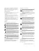
2. Install the tray in the cabinet (FIGURE 2-1). Front Rear FIGURE 2-1 ! Installing the Tray in the Cabinet Caution – Use only SAE 10-32 screws to secure the tray to the cabinet mounting rails. Using any other screw type will damage the cabinet mounting holes. a. In the front of the tray, use the Phillips screwdriver to loosely install two 10-32 screws each for the left and right side. b.
2.3.4 Installing the Hub on the Mounting Tray 1. Determine on which side of the tray you are going to install the hub. The first hub goes in position A; the second goes in position B. 2. From the rear of the tray, slide the hub mounting bracket into the slots in the mounting tray (FIGURE 2-2) You should hear a click as the black plastic retaining tab goes through the notch in the tray.
2.3.5 Installing GBICs and Fiber Optic Cables 1. Choose the hub port into which you will install the GBIC. Although the ports in a hub are electrically equivalent, follow any configuration guidelines that may have accompanied the other hardware in your configuration. If you are connecting the GBIC to a Sun StorEdge A5000 Disk Array , refer to the Sun StorEdge A5000 Disk Array Hardware Configuration Guide, part number 805-0264-xx. 2. Insert the GBIC into the port.
■ To insert a GBIC that has a bail, slide the GBIC into the available port with the bail in the unlocked (right) position. Once the GBIC is firmly seated in the port, move the bail left into the locked position. Slot Bail Notches Key (on side) FIGURE 2-4 Installing a GBIC That Has a Bail and Fiber Optic Cable 3. Connect the fiber optic cable to the GBIC. Fiber optic cable connectors are keyed to prevent improper insertion; they can only be installed as shown in FIGURE 2-3 and FIGURE 2-4. 4.
1. Connect the female end of the power cord to the power receptacle at the rear of the hub (FIGURE 1-1 on page 1-2). 2. Route the power cord down the right side and along the bottom of the cabinet. 3. Route the power cord up through the cutout to the power distribution unit at the left side of the cabinet. Caution – The power distribution unit serves as the primary disconnect device for the hub. Do not connect the hub into a power source other than the power distribution unit.
2.3.8 Reassembling the Cabinet Follow the instructions in your system or expansion cabinet documentation. If necessary, be sure to: ■ ■ ■ 2.4 Replace or close the top front panel Replace or close the rear panel Push the antitilt bar back into the cabinet Troubleshooting If a GBIC is properly installed, the Device Active LED for the GBIC should be on and the Bypass LED should be off. If the Device Active LED for a GBIC is flashing, replace the GBIC.
CHAPTER 3 Service This chapter describes how to remove and install a GBIC. It also describes how to remove a hub. 3.1 Installing a GBIC 1. Choose the hub port into which you will install the GBIC. Although the ports in a hub are electrically equivalent, follow any configuration guidelines that may have accompanied the other hardware in your configuration.
■ To insert a GBIC that does not have a bail, slide the GBIC into the port until you hear a click.
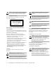
■ To insert a GBIC that has a bail, slide the GBIC into the available port with the bail in the unlocked (right) position. Once the GBIC is firmly seated in the port, move the bail left into the locked position. Slot Bail FIGURE 3-2 Installing a GBIC That Has a Bail 3. Connect the fiber optic cable to the GBIC.
3.2 Removing a GBIC 1. Disconnect the fiber optic cable from the GBIC (FIGURE 3-3 or FIGURE 3-4). 2. Remove the GBIC. Sun currently ships two types of GBICs: one with a bailed locking mechanism and one without. ■ To remove a GBIC that does not have a bail, push the module tabs together and pull the GBIC out from the port.
■ To remove a GBIC that has a bail, move the bail right to the unlocked position and pull on the plastic tab of the bail.
3.3 Removing a Hub 1. Disconnect and remove any installed fiber optic cables or GBICs ( FIGURE 3-3). 2. Disconnect the AC power cord from the hub. 3. Push up on the retaining tab that secures the hub to the mounting tray (FIGURE 3-5). Position A Position B Notch Retaining tab FIGURE 3-5 Removing the Hub 4. Pull the hub back and then lift it out of the mounting slots.
APPENDIX A Specifications A.1 Physical TABLE A-1 Physical Specifications Height Width Depth Weight 1.69 in 8.6 in 14.35 in 6 lbs 42.92 mm 218.4 mm 364.49 mm 2.
A.2 Electrical TABLE A-2 Electrical Specifications Specification Value Voltage 95 to 120V Frequency 50 to 60 Hz Power Consumption Empty Full 25W 35W1 Line Current Average Surge (Peak) 350 mA1 1.0 A ( < 1 second)1 1. All ports in use @250 mA each, steady state at 120 Vrms, 60 Hz A.3 Environmental TABLE A-3 A-2 Environmental Specifications Specification Operating Value Temperature 0C to 50C Vibration 1.