
Computer Accessories User Manual


Chapter 2 Hardware Installation 23
Removing and Installing Modules
This chapter describes how to remove and insert:
■ CPUset, PCI, CAF and PSU modules (“To Remove a Module” on page 24)
■ CPUset modules: “CPUset Modules” on page 25
■ PCI modules: “PCI Modules” on page 28
■ CAF modules: “CAF Modules” on page 27
■ PSU modules: “PSU Modules” on page 29
■ Drive chassis (“Replacing a Disk Chassis” on page 32)
■ Removable media module (“Replacing an RMM” on page 30)
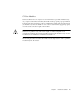
Caution – The wrist-strap provided must be used when replacing modules, or
making cable connections to the rear of the system. The wrist-strap connection point
on the Netra ft 1800 system is located on the panel at the bottom rear of the chassis.
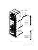
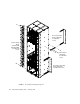
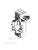
All modules have their own guides in slots in the chassis, into which they fit exactly.
No module will fit into a slot allocated to a different class of module. No module
will fit into its own slot if it is upside down.
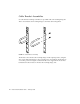
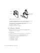
Module Injector/Ejector Mechanisms
All the modules except the disk chassis (DSK) and RMM have an injector/ejector
lever (CPUset modules have two). They are all similar in function and usage. A
common feature is a slide which engages and disengages the module’s electrical
connection to the motherboard, and a lever which physically engages and
disengages the module. When the latch is disengaged, a red dot is exposed. This
facilitates the identification of unlatched injectors.