
Interface Adapter User's Guide


Appendix A Cable Pin Assignments & Signals 25
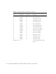
38 CTS2(B) 27 Port 2 Clear To Send
39 RxC2(A) 8 Port 2 Receive Clock
40 RxC2(B) 26 Port 2 Receive Clock
Shield Ground SG 1 Port 2 Shield Ground and Signal
ground
41 RxD3(A) 6 Port 3 Receive Data
42 RxD3(B) 24 Port 3 Receive Data
43 DTR3(A) 12 Port 3 Data Terminal Ready
44 DTR3(B) 30 Port 3 Data Terminal Ready
45 TxD3(A) 4 Port 3 Transmit Data
46 TxD3(B) 22 Port 3 Transmit Data
47 RTS3(A) 7 Port 3 Request To Send
48 RTS3(B) 25 Port 3 Request To Send
49 TxC3(A) 17 Port 3 Transmit Clock
50 TxC3(B) 35 Port 3 Transmit Clock
51 TxCI3(A) 5 Port 3 Transmit Clock In
52 TxCI3(B) 23 Port 3 Transmit Clock In
53 DCD3(A) 13 Port 3 Data Carrier Detect
54 DCD3(B) 31 Port 3 Data Carrier Detect
55 DSR3(A) 11 Port 3 Data Set Ready
56 DSR3(B) 29 Port 3 Data Set Ready
57 CTS3(A) 9 Port 3 Clear To Send
58 CTS3(B) 27 Port 3 Clear To Send
59 RxC3(A) 8 Port 3 Receive Clock
60 RxC3(B) 26 Port 3 Receive Clock
Shield Ground SG 1 Port 3 Shield Ground and Signal
Ground
61 RxD4(A) 6 Port 4 Receive Data
62 RxD4(B) 24 Port 4 Receive Data
63 DTR4(A) 12 Port 4 Data Terminal Ready
64 DTR4(B) 30 Port 4 Data Terminal Ready
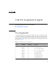
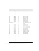
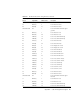
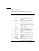
TABLE A-1 RS-449 Connector Pin Assignments (Continued)
80-Pin Amp.
Pin No.
RS-449
Signal Name
RS-449
DB-37 Pin No. Description