
Network Card User Manual

Chapter 2 Installing the Rear-Access Adapter 15
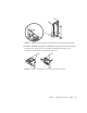
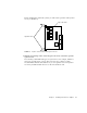
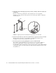
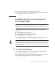
FIGURE 2-7 Ejection Levers Installed in the Slot’s Cutouts (Two Types of Levers)
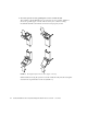
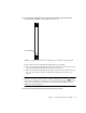
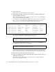
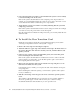
9. Using a No. 0 Phillips screwdriver, tighten the captive screws inside the card’s top
and bottom ejection levers.
The card may contain different types of ejection levers. For example,
FIGURE 2-8
shows two possible types of levers.
FIGURE 2-8 Tightening the Ejection Lever Captive Screws (Two Types of Levers)
Cutouts
Tabs
Tabs