
Server User Manual
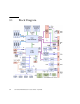

Table Of Contents
- Sun Netra™ CP3250 Blade Server User’s Guide
- Contents
- Figures
- Tables
- Preface
- Overview
- Hardware Installation and Service
- 2.1 Safety and Tool Requirements
- 2.2 Installing the Blade Server
- 2.3 Service Procedures
- 2.3.1 Hot-Swapping the Netra CP3250 Blade Server
- 2.3.2 Powering Off the Netra CP3250 Blade Server
- 2.3.3 Removing the Netra CP3250 Blade Server
- 2.3.4 Powering On the System
- 2.3.5 Automatic Power-Off Events
- 2.3.6 Servicing DIMMs
- 2.3.7 Installing the Optional Compact Flash Card
- 2.3.8 Installing Optional AMC
- 2.3.9 Adding or Replacing the Battery
- 2.3.10 Changing Jumper Settings
- 2.3.11 Checking DIP Switch Settings
- 2.3.12 Resetting the Netra CP3250 Blade Server
- Hardware Architecture
- Software Configuration
- Configuring and Using BIOS Firmware
- 5.1 About BIOS Settings
- 5.2 Changing the Configuration of a BIOS Menu Item
- 5.3 Setting the Boot Device Using BIOS Setup Screens
- 5.4 Setting Supervisor and User Passwords
- 5.5 Resetting the System Time and System Date
- 5.6 Updating the BIOS
- 5.7 Secondary BIOS Image
- 5.8 Perform a Live Firmware Upgrade
- 5.9 Power-On Self-Test
- 5.10 Changing POST Options
- BIOS Screens
- Physical Characteristics
- ShMM CLI and Commands
- Index

Chapter 3 Hardware Architecture 3-7
3.5.5 Trusted Platform Module (TPM)
The Sun Netra CP3250 blade server provides a Trusted Platform Module (TPM) chip,
which enables various security features, including hardware and software
authentication. This chip is reserved for future use on the Sun Netra CP3250 blade
server.
3.5.6 IPMC
The H8S/2166 IPMC provides the IPM controller function on the Sun Netra CP3250
blade server. The IPMC provides PICMG 3.0 board management functionality, and
interfaces to the payload through a serial interface.
The IPMC provides the following:
■ Dual buffered IPMB interfaces to connect to IPMB-0
■ Hot-swap latch input and LED control
■ Payload power control
■ Payload base and fabric interface e-keying control
■ Payload power and temperature monitoring
3.5.7 RS-232 Serial Ports
A Serial port is available on the front panel using an RJ-45 connector. This same port
is also wired through the Zone 3 connectors to provide a copy of this port on the
ARTM. This connector shares the SuperIO chip Port A with the H8-IPMI controller,
to allow console messages to be directed to the H8 when the external ports are not in
use. The blade server detects a valid RS232 connection to either the front or rear port
and will automatically disconnect the SuperIO port from the H8 and connect to the
external ports.
Note – The front and rear ports cannot be used at the same time because they share
the same wires.