SunFDDI/P™ 1.0 Adapter User’s Guide Sun Microsystems Computer Company A Sun Microsystems, Inc. Business 2550 Garcia Avenue Mountain View, CA 94043 USA 415 960-1300 fax 415 969-9131 Part No.
Copyright 1997 Sun Microsystems, Inc. 2550 Garcia Avenue, Mountain View, California 94043-1100 U.S.A. All rights reserved. This product or document is protected by copyright and distributed under licenses restricting its use, copying, distribution, and decompilation. No part of this product or document may be reproduced in any form by any means without prior written authorization of Sun and its licensors, if any. Portions of this product may be derived from the UNIX® system and from the Berkeley 4.
Regulatory Compliance Statements Your Sun product is marked to indicate its compliance class: • • • Federal Communications Commission (FCC) — USA Department of Communications (DOC) — Canada Voluntary Control Council for Interference (VCCI) — Japan Please read the appropriate section that corresponds to the marking on your Sun product before attempting to install the product. FCC Class A Notice This device complies with Part 15 of the FCC Rules. Operation is subject to the following two conditions: 1.
DOC Class A Notice - Avis DOC, Classe A This Class A digital apparatus meets all of requirements the Canadian Interference-Causing Equipment Regulations. Cet appareil numérique de la classe A respecte toutes les exigences du Règlement sur le matériel brouilleur du Canada. DOC Class B Notice - Avis DOC, Classe B This Class B digital apparatus meets all of requirements the Canadian Interference-Causing Equipment Regulations.
Declaration of Conformity Compliance ID: PCI-S10-100 Product Name: SunFDDI/P SAS Adapter This equipment complies with Part 15 of the FCC Rules. Operation is subject to the following two conditions: 1) This equipment may not cause harmful interference and 2) This equipment must accept any interference that may cause undesired operation.
Declaration of Conformity Compliance ID: PCI-D10-100 Product Name: SunFDDI/P DAS Adapter This equipment complies with Part 15 of the FCC Rules. Operation is subject to the following two conditions: 1) This equipment may not cause harmful interference and 2) This equipment must accept any interference that may cause undesired operation.
Contents Preface. . . . . . . . . . . . . . . . . . . . . . . . . . . . . . . . . . . . . . . . . . . . . . . . . . . . xix Part 1 —Installing and Configuring SunFDDI/P 1. SunFDDI/P Overview . . . . . . . . . . . . . . . . . . . . . . . . . . . . . . . . . 1 Feature Summary. . . . . . . . . . . . . . . . . . . . . . . . . . . . . . . . . . . . . . 1 FDDI Conformance . . . . . . . . . . . . . . . . . . . . . . . . . . . . . . . . . . . . 2 2. Hardware Installation . . . . . . . . . . . . . . . . . .
viii 3. Installing SunFDDI/P Software . . . . . . . . . . . . . . . . . . . . . . . . . 11 Installation Requirements . . . . . . . . . . . . . . . . . . . . . . . . . . . . . . . 12 Declaring IP Addresses for SunFDDI/P . . . . . . . . . . . . . . . . . . . 12 Installing and Configuring SunFDDI/P . . . . . . . . . . . . . . . . . . . 13 ▼ To Load and Mount the CD-ROM . . . . . . . . . . . . . . . . . . 13 ▼ To Install SunFDDI/P Using pkgadd . . . . . . . . . . . . . . .
Tuning the High and Low Water Marks at Boot Time. . . . . 29 Tuning the Socket Options . . . . . . . . . . . . . . . . . . . . . . . . . . . 29 MTU Path Discovery . . . . . . . . . . . . . . . . . . . . . . . . . . . . . . . . 30 ▼ To Tune the Maximum Transfer Unit (MTU) . . . . . . . . . 30 ▼ To Disable MTU Path Discovery . . . . . . . . . . . . . . . . . . . 31 ▼ To Tune the Target Token Rotation Time (TTRT) . . . . . . 31 5. Troubleshooting and Diagnostics . . . . . . . . . . . . . . . . . .
x FDDI Network Model . . . . . . . . . . . . . . . . . . . . . . . . . . . . . . . . . . 50 Physical Medium Dependent (PMD) Layer . . . . . . . . . . . . . 51 Physical (PHY) Layer . . . . . . . . . . . . . . . . . . . . . . . . . . . . . . . 51 Media Access Control (MAC) Layer . . . . . . . . . . . . . . . . . . . 52 Station Management (SMT) Layer . . . . . . . . . . . . . . . . . . . . . 52 Communication Between FDDI Layers . . . . . . . . . . . . . . . . 53 FDDI Network Architecture . . . . .
Disadvantages . . . . . . . . . . . . . . . . . . . . . . . . . . . . . . . . . . . . . 75 Tree of Concentrators. . . . . . . . . . . . . . . . . . . . . . . . . . . . . . . . . . . 75 Advantages. . . . . . . . . . . . . . . . . . . . . . . . . . . . . . . . . . . . . . . . 76 Disadvantages . . . . . . . . . . . . . . . . . . . . . . . . . . . . . . . . . . . . . 77 Ring of Trees . . . . . . . . . . . . . . . . . . . . . . . . . . . . . . . . . . . . . . . . . . 77 Advantages. . . . . . . . . . .
▼ To Install the Standard SNM Agents on a Client . . . . . . 104 ▼ To Install the FDDI Schemas on a Client . . . . . . . . . . . . 105 Installing the FDDI Schemas on the Console . . . . . . . . . . . . 106 ▼ To Share pf_install_agents From a Client . . . . . . . 107 Managing FDDI Networks with SunNet Manager . . . . . . . . . . 109 ▼ To Set Up the SunNet Manager Console. . . . . . . . . . . . . 109 Using the SunFDDI/P Local Agent (pf_fddi) . . . . . . . . .
Glossary . . . . . . . . . . . . . . . . . . . . . . . . . . . . . . . . . . . . . . . . . . . . . . . . . . 141 Index . . . . . . . . . . . . . . . . . . . . . . . . . . . . . . . . . . . . . . . . . . . . . . . . . . . . .
xiv SunFDDI/P 1.
Figures Figure 2-1 Aligning SC-Type Fiber Optic Cable Connectors . . . . . . . . . . . 6 Figure 2-2 Cleaning the End of a Fiber Optic Cable . . . . . . . . . . . . . . . . . . 8 Figure 6-1 FDDI Architectural Model . . . . . . . . . . . . . . . . . . . . . . . . . . . . . . 50 Figure 6-2 Communication Between FDDI Layers . . . . . . . . . . . . . . . . . . . 54 Figure 6-3 Basic FDDI Network Architecture . . . . . . . . . . . . . . . . . . . . . . .
xvi Figure 7-2 Basic Dual-Ring Network with Two Faults. . . . . . . . . . . . . . . . 71 Figure 7-3 Standalone Concentrator . . . . . . . . . . . . . . . . . . . . . . . . . . . . . . . 72 Figure 7-4 Standalone Concentrator With Dual-Homing . . . . . . . . . . . . . 74 Figure 7-5 Hierarchical Tree of Concentrators . . . . . . . . . . . . . . . . . . . . . . . 76 Figure 7-6 Ring of Trees. . . . . . . . . . . . . . . . . . . . . . . . . . . . . . . . . . . . . . . . . .
Tables Table 5-1 Problems Installing SunFDDI/P . . . . . . . . . . . . . . . . . . . . . . . . . 39 Table 5-2 Problems Running SunFDDI/P. . . . . . . . . . . . . . . . . . . . . . . . . . 40 Table 5-3 Problems Using the SNM Agents for SunFDDI/P . . . . . . . . . . 43 Table 8-1 pf_stat States Under the ECM Heading. . . . . . . . . . . . . . . . . 90 Table 8-2 pf_stat States Under the RMT Heading. . . . . . . . . . . . . . . . . 90 Table 8-3 pf_stat States Under the PCM Heading. . . . . . . .
xviii SunFDDI/P 1.
Preface The SunFDDI/P™ 1.0 Adapter User’s Guide describes how to turn your system into an FDDI station attached to an FDDI network. It is intended for experienced network administrators who are familiar with the Solaris 2.5.1 Hardware: 4/97 operating environment. The SunFDDI/P 1.0 Adapter is supported on Sun-4u PCI-based system architectures. How this Book is Organized The SunFDDI/P™ 1.
The connector type has been changed for SunFDDI/P to an SC-type connector. If you are connecting the SunFDDI/P card to a network that has a MIC connector, an SC-MIC converter cable is required. Part 1 — “Installing and Configuring SunFDDI/P” Chapter 1, “SunFDDI/P Overview,” describes the SunFDDI/P 1.0 implementation of the FDDI protocols and includes a list of the specifications to which it conforms.
Chapter 9, “Managing FDDI Stations Using SunNet Manager,” describes how to install the SunNet Manager agents for SunFDDI/P and how to set up the SunNet Manager console to manage them. Chapter 10, “Developing Applications that Run over SunFDDI/P,” describes how to create applications that run over SunFDDI/P, using the DLPI interface for a Solaris 2.x environment.
Typographic Conventions The following table describes the typographic changes used in this book. Typeface or Symbol Meaning Example AaBbCc123 The names of commands, files, and directories; on-screen computer output Edit your .login file. Use ls -a to list all files. machine_name% You have mail. AaBbCc123 What you type, contrasted with on-screen computer output AaBbCc123 Command-line placeholder: replace with a real name or value To delete a file, type rm filename.
Related Documents For a more detailed description of FDDI technology and the relevant FDDI protocols, see these documents: Title Author/Publisher Part Number Handbook of Computer-Communications Standards, Volume 2, William Stallings, Macmillan Publishing Company: 1987 NA Edited by Sonu Mirchandani and Raman Khanna, John Wiley & Sons: 1993 NA Amit Shah and G. Ramakrisnan, Prentice Hall, Inc.
Getting Help For technical assistance in the United States, call 1-800-872-4786. To get the latest patches and patch revisions, contact your local Sun Service provider. For additional information, access Sun on the World Wide Web: http://www.sun.com and select Sales & Service ➤ On-line support ➤ SunSolve Online™ ➤ Patches. Sun Welcomes Your Comments Please use the Reader Comment Card that accompanies this document. We are interested in improving our documentation and welcome your comments and suggestions.
Part 1 — Installing and Configuring SunFDDI/P
1 SunFDDI/P Overview Feature Summary page 1 FDDI Conformance page 2 This chapter describes the Sun FDDI (Fiber Distributed Data Interface) implementation of the FDDI protocols, including a list of the ANSI/FDDI standards to which it conforms. See Chapter 6, “FDDI Network Architecture” for more information on FDDI architecture. Feature Summary The SunFDDI/P 1.0 product is a combination of hardware and software that turns your system into an FDDI station.
1 • Provides connection to multimode fiber (SunFDDI/P and SunFDDI/P Dual) networks • • • Supports data transfer rates of up to 100 Mbps • Supports up to four SunFDDI/P PCI cards installed in one PCI bus and up to eight SunFDDI/P PCI cards installed in one machine • Conforms to the 32-bit Peripheral Component Interconnect (PCI) specification for short form adapter cards • • • Supports 33 MHz operating frequency and 5.0 volt I/O signaling • Complies with the ANSI X3T9.
2 Hardware Installation Device Instances and Device Names page 4 Installing SunFDDI/P Adapter Cards page 5 Connecting Fiber Optic Cables page 5 Link Status Indicator (Diagnostic LED) page 9 This chapter tells you where to find step-by-step procedures for installing PCI cards. It describes the convention used to assign device names to SunFDDI/P adapter cards, and tells you how to connect fiber optic cables.
2 Device Instances and Device Names You can install a SunFDDI/P PCI card in any available master PCI slot. SunFDDI/P supports up to four SunFDDI/P PCI cards installed in one PCI, and up to eight SunFDDI/P PCI cards installed in one machine. SunFDDI/P 1.0 PCI cards are assigned device names of the form pf, where the instance number is determined by the number and relative positions of the cards installed.
2 Installing SunFDDI/P Adapter Cards ! Caution – The SunFDDI/P PCI card is sensitive to static electricity. Always use the wrist strap supplied with SunFDDI/P when handling the card and ensure that the wrist strap is properly grounded. Handle the SunFDDI/P PCI card by the edges, and avoid touching any of the components. Refer to the hardware installation manual that came with your system for detailed instructions on how to install an adapter card in your machine.
2 • Fiber optic cable has a limited turn radius. Do not bend it in a way that could damage the fiber or cause signal loss. ▼ To Connect the Fiber Optic Cable 1. Unpack the cable, remove the plastic protective caps or plugs from each end, and remove the plug from the transceiver unit on the card. 2. Orient the fiber optic cable to the connector on the SunFDDI/P card. Most fiber optic cables have raised keys on one side of the connectors (see Figure 2-2).
2 MIC-to-MIC Coupler A separate MIC (Media Interface Connector) coupler is shipped with the SunFDDI/P 1.0 Adapter product to support MIC-to-MIC network connections. Two different versions of the coupler are available: • • One with raised keys to help you properly orient the connection One without raised keys, which has specific connecting instructions Note – Make sure you properly connect the coupler. An improper connection will “twist” or “cross” the ring.
2 ▼ To Clean the Fiber Optic Cable 1. Gently wipe the end of the ferrule with an alcohol-moistened cotton swab. Figure 2-2 Cleaning the End of a Fiber Optic Cable 2. Blow clean, dry compressed air around the end of the connector and around the ferrule to dislodge loose dust and grit. 3. Clean the adapter by running a pipe cleaner moistened in alcohol running though it. Repeat with a dry pipe cleaner. 4. Dry the adapter with clean, dry compressed air. 8 SunFDDI/P 1.
2 Link Status Indicator (Diagnostic LED) A link status indicator is mounted on the SunFDDI/P PCI card. The color of the LED indicates the current status of the connection to the FDDI network as follows: • No LED lit: Either the driver is loaded and the interface is not configured or the driver has not been loaded. • Amber: Interface configured, no valid line state to an active FDDI network exists. • • Green: Connection established to an active FDDI network. • Red: Adapter fails FDDI path test.
2 10 SunFDDI/P 1.
3 Installing SunFDDI/P Software Installation Requirements page 12 Declaring IP Addresses for SunFDDI/P page 12 Installing and Configuring SunFDDI/P page 13 Installing SunNet Manager Agents for SunFDDI/P page 20 Removing SunFDDI/P page 22 This chapter assumes that you have already installed the SunFDDI/P adapter card in your machine and that you are loading the software from a local CD-ROM drive.
3 Installation Requirements • Hardware and Software Platforms SunFDDI/P is designed for Sun-4u PCI-based system architectures (32 Mbytes RAM minimum) running a Solaris 2.5.1 Hardware: 4/97 environment. • Disk Space A machine with 1600 KBytes of disk space is required to install SunFDDI/P. • Host names and IP Addresses A unique host name and IP address must be assigned to each SunFDDI/P device installed in your machine.
3 Installing and Configuring SunFDDI/P Use pkgadd(1M) to install unbundled software. See the Solaris 2.5 Software and AnswerBook Packages Administration Guide for detailed information on installing software products using pkgadd. For detailed instructions on how to load software from a CD-ROM drive mounted on a remote directory, see the Solaris 2.5 Software and AnswerBook Packages Administration Guide. ▼ To Load and Mount the CD-ROM 1. Log in as root or become superuser. 2.
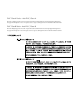
3 3. Enter the number that corresponds to the package you want to install and press Return. Respond to any prompts that are displayed. Two packages are associated with SunFDDI/P. They contain the device drivers and utilities used to manage your SunFDDI/P station. The following packages are available: 1 SUNWpfr SunFDDI/P (Driver) (sparc) 1.0 2 SUNWpft SunFDDI/P (Man Pages/Utilities) (sparc) 1.0 Select package(s) you wish to process (or “all” to process all packages).
3 Is this install for a diskless client [n] [y,n,?] (See Chapter 11, “Setting Up Servers and Diskless Clients” for more information on booting diskless clients across an FDDI network.) The number of SunFDDI/P interfaces found is displayed and you are asked how many interfaces you want to configure. 2. Enter a number from 1 to 16 or press Return for the default. How many FDDI (pf) interfaces do you want to configure? 3. Type the host name for which you want the interface associated.
3 • Type n, or press Return, if you are not using SunNet Manager to manage your network; if you are running SunNet Manager agents on another machine; or if you want to start the SunNet Manager agents manually. Do you want to start the SunNet Manager daemons for SunFDDI at boot time? [n] [y,n,?,q] y 7. Type y to use the installation scripts with superuser permission. This package contains scripts which will be executed with superuser permission during the process of installing the package.
3 1. Type y to accept the installation of files with setuid/setgid permission. If you are installing the SUNWpft package for the first time, this step will not occur. Do you want to install these setuid/setgid files [y,n,?,q] y 2. Type y to accept the installation scripts with superuser permission. This package contains scripts which will be executed with superuser permission during the process of installing the package.
3 • If Volume Manager (vold) is not running on your machine, unmount the CD-ROM before you eject and remove the directory that you created: # /usr/sbin/umount /cdrom/sunfddip_1_0 # eject cdrom # rmdir /cdrom/sunfddip_1_0 3. Reboot your machine. ▼ To Check the Installation 1. Use netstat(1M) to check for SunFDDI/P interfaces.
3 Your SunFDDI/P station should now be active, and you should be able to send and receive data across an FDDI connection. For optimum performance from your FDDI network, you may need to tune the configurable network parameters. See Chapter 4, “Improving Network Performance,” for detailed instructions. If you have problems configuring or using your SunFDDI/P station, see Chapter 5, “Troubleshooting and Diagnostics,” for help. ▼ Unloading Drivers The driver for the SunFDDI/P 1.
3 Installing SunNet Manager Agents for SunFDDI/P Use pf_install_agents to install the SunNet Manager agents for SunFDDI/P. This script copies the FDDI schema files to the directory in which the standard agents are installed and updates the configuration files for SunNet Manager. Run pf_install_agents on each SunNet Manager Console, and on each SunFDDI/P station you want to manage using SunNet Manager. ▼ To Use pf_install_agents 1. Log in as root or become superuser. 2.
3 4. Specify the destination directory for the SunFDDI/P schemas. SunNet Manager looks for the schemas in the directory /SUNWconn/snm/agents. The variable is set to /opt by default. If you installed the SunNet Manager agents and libraries on the FDDI station, or if you used getagents to recover the agents from the console, then this directory exists. Enter the base directory under which you installed the SunNet Manager agents as the destination directory for the SunFDDI/P schemas.
3 Removing SunFDDI/P If you remove the SunFDDI/P hardware interfaces from your machine, you also need to remove the SunFDDI/P software to prevent the device driver from starting each time you reboot the machine. Use pkgrm(1M) to remove unbundled software from machines running a Solaris 2.x environment. Refer to Installing Solaris Software for detailed information on removing software packages using pkgrm. ▼ To Remove SunFDDI/P 1. Log in as root or become superuser. 2. Use pkgrm to remove SunFDDI/P.
4 Improving Network Performance High Performance FDDI Networks page 24 Ring Latency Improvement page 24 Data Throughput Improvement page 25 Performance Across Bridges page 25 Target Token Rotation Time (TTRT) page 26 Improving Performance page 27 This chapter tells you how to optimize your FDDI network and assumes that you are familiar with FDDI network architecture and related terminology.
4 High Performance FDDI Networks FDDI networks increase the potential to carry more information, rather than create faster connections. If the applications running over the network do not use the available bandwidth efficiently, you will not see much improvement in the performance of your network by using FDDI. You can obtain optimum performance by balancing the complementary objectives of maximum throughput and minimum access delay: • Throughput is a measure of the ring use.
4 Data Throughput Improvement The most significant improvements in throughput are achieved by maximizing the rate at which data is transferred to and from the FDDI network. If you are running TCP/IP or UDP/IP applications, you can improve throughput by modifying the parameters that control the rate at which these protocols transfer data to and from the SunFDDI/P device driver—that is, between user space and kernel space.
4 fragmented so that they do not exceed the MTU of the Ethernet network. Some low-cost bridges that do not support fragmentation will reject the 4352-byte packets. Fragmenting and reassembling the packets introduces a considerable overhead that affects performance. It also increases the risk of out-of-sequence or dropped packets.
4 Improving Performance The following section describes how to modify the user-configurable network parameters. To obtain optimum network performance, you may need to tune these parameters, depending on your network configuration and the type of network traffic. Changing the High and Low Water Marks The maximum rate at which data is transferred between user space and kernel space by applications that use STREAMS is controlled by the high water marks.
4 3. Use ndd —set to modify the current value of the TCP high water marks (tcp_xmit_hiwat and tcp_recv_hiwat). For optimum performance over FDDI connections, the TCP high water marks should both be set to 32 Kbytes. # ndd —set /dev/tcp tcp_xmit_hiwat 32768 # ndd —set /dev/tcp tcp_recv_hiwat 32768 4. Use ndd —get (the default) to check the current value of the UDP high water marks (udp_xmit_hiwat and udp_recv_hiwat). # ndd —get /dev/udp udp_xmit_hiwat 8192 # ndd —get /dev/udp udp_recv_hiwat 8192 5.
4 2. Use ndd —set to modify the current value of the TCP and UDP low water marks (tcp_xmit_lowat and udp_xmit_lowat). For optimum performance over FDDI connections, set the TCP and UDP low water marks to 24 Kbytes. # ndd —set /dev/tcp tcp_xmit_lowat 24576 # ndd —set /dev/udp udp_xmit_lowat 24576 Tuning the High and Low Water Marks at Boot Time Each time you reboot your machine, the high and low water marks are reset to their default values.
4 MTU Path Discovery Machines running a Solaris 2.x environment support MTU path discovery, which allows the optimum MTU to be negotiated. Under most circumstances, this ensures efficient use of the network resources. However, to enable MTU path discovery to work, the “don’t fragment” bit in the packet is set, which causes a problem with some bridges and routers that do not support this feature.
4 ▼ To Disable MTU Path Discovery Many bridges do not support MTU path discovery. ♦ To disable this feature in order to transmit packets across a bridge, type: # ndd —set /dev/ip ip_path_mtu_discovery 0 MTU path discovery is re-enabled each time the machine is rebooted. ▼ To Tune the Target Token Rotation Time (TTRT) The target token rotation time (TTRT) for the network is the lowest value of T_req bid during the claim process. Follow these steps to change the value of T_req bid: 1.
4 32 SunFDDI/P 1.
5 Troubleshooting and Diagnostics Troubleshooting Checklist page 34 Solving Common Problems page 39 Running the Hardware Self-Test Program page 44 Loading the Device Driver Manually page 45 This chapter describes how to detect and resolve common problems with your FDDI network. It includes instructions on how to load and configure the SunFDDI/P device driver manually, if required.
5 Troubleshooting Checklist Use the following checklist to verify the major components of your SunFDDI/P station, and to check that it is installed, configured, and attached to the network correctly. ▼ To Check the Connection to the Station ♦ Check that the cable connector is seated firmly into the plug on the SunFDDI/P adapter card. You should feel the connector “click” into place.
5 • If the LED is amber, the SunFDDI/P driver is loaded, the pf interface is configured, but no valid line state to an active FDDI network exists. a. Check the physical connections between the station and the ring, or the station and the concentrator. b. Check the status of the neighboring station. If this station is down, it will bring down the link between the stations. • • If the LED is red, the adapter failed the FDDI path test.
5 ▼ To Check the SunFDDI/P Driver ♦ Use netstat(1M) to check that the SunFDDI/P (pf) driver is installed correctly, and to check for an excessive number of errors and collisions: SunFDDI interface pf ----> % netstat -i Name Mtu Net/Dest Queue lo0 8232 loopback le0 1500 our-lan pf0 4352 our-fddi Address localhost hysop hysop-pf Ipkts Ierrs Opkts Oerrs Collis 21 2146 1086 0 0 0 21 950 907 0 1 0 0 13 0 0 0 0 A sudden increase in the number of errors could indicate a noisy connection caused by a
5 ▼ To Check the IP Routing 1. Check the IP routing table using the netstat(1M) command: % netstat —nr 2. Check that the FDDI subnetwork is featured in the routing table. If the routing table is empty, check that the routing daemon (in.routed) is running on your machine. ▼ To Check the Protocol Statistics ♦ Use netstat(1M) to check the per-protocol (IP, TCP, UDP, etc.
5 ♦ Use netstat(1M) to check the driver statistics: # netstat -k pfo ipacket = x, ierror = y, opackets = z . . . ▼ To Check the SMT Traffic If the target station is not running SunFDDI/P, it does not necessarily support the same set of SMT frames. If the target station receives an SMT request for an unsupported service, it issues a Request Denied Frame (RDF). ♦ Use pf_smtmon(1M) to examine the SMT frames: # /pf_smtmon [-i pf] [—x] [—h] [] 38 SunFDDI/P 1.
5 Solving Common Problems Use the information in Table 5-1 and Table 5-2 to diagnose and resolve some of the common problems that can occur when installing, configuring, or running SunFDDI/P. Table 5-1 Problems Installing SunFDDI/P Problem Action The SunFDDI/P software package (SUNWpfr) cannot be found. Check that you have inserted the CD-ROM in the CD-ROM drive and that the CD-ROM is mounted on a local directory.
5 Table 5-2 Problems Running SunFDDI/P Problem Action The link status indicator (diagnostic LED) remains red. Check that the SunFDDI/P software is installed correctly and that the driver is loaded and configured. The link status indicator (diagnostic LED) remains amber. Check that the SunFDDI/P PCI card is connected to the network. The link status indicator (diagnostic LED) remains amber, even after the local station is connected to the network and the driver is configured and loaded.
5 Table 5-2 Problems Running SunFDDI/P (Continued) Problem Action Running pf_stat without the —m option (to display information about the local station) shows that the ring is ISOLATED. Check that the link status indicator is green, indicating that the SunFDDI/P interface is attached to an active network. Check the connections to neighboring stations or the concentrator. Some concentrators have diagnostic LEDs that indicate if the ring is operating correctly.
5 Table 5-2 Problems Running SunFDDI/P (Continued) Problem Action The local station cannot reach FDDI stations located on a remote Ethernet network. Check that the IP address and host name of the remote station is entered in the NIS map or NIS+ tables (or in /etc/hosts on each remote station if you are not running NIS or NIS+). If you are operating in a Solaris 2.x environment, which uses MTU path discovery, check that packets are being transmitted across the bridge between the networks.
5 Table 5-2 Problems Running SunFDDI/P (Continued) Problem Action Running pf_smtmon shows the frequent occurrence of request denied frames (RDF). The SMT entity on one of the remote stations does not support the same set of SMT services. This should not occur on a station running SunFDDI/P. You can use this facility to detect problems communicating with a remote station using the SunNet Manager proxy agent.
5 Running the Hardware Self-Test Program If you suspect that there may be a problem with the SunFDDI/P adapter card, you can use the built-in hardware self-test to check the state of its primary components and the connection to the network. ▼ To Run the Hardware Self-Test 1. Log in as root or become superuser. 2. Halt the machine. # sync;sync;halt 3. At the boot prompt, type: ok test /pci/pf Local MAC Address 0:80:d8:10:3:ed (Canonical) Interrupt register read/write test ....
5 Loading the Device Driver Manually Normally, the SunFDDI/P device driver is loaded and configured by the post-installation script, which is launched automatically when the software is installed. If you encounter problems when running this script, or if you want to customize the installation, you may need to load the device driver manually. ▼ To Configure and Load the Device Driver 1. Log in as root or become superuser. 2. Check that there are no partially installed drivers for SunFDDI/P. a.
5 b. Look in the /dev directory for links to these entries: ls -l /dev | grep pf lrwxrwxrwx 1 root other pf -> ../devices/pseudo/clone@0:pf 5. Create a file called /etc/hostname.pf for each SunFDDI/P IP interface that you configure. Each file must contain the host name assigned to the IP interface. These files are used to configure the interfaces when the system is rebooted.
Part 2 — Planning and Implementing SunFDDI Networks
6 FDDI Network Architecture FDDI Network Model page 50 FDDI Network Architecture page 55 FDDI Failure Recovery page 60 FDDI Ring Operation page 65 FDDI Performance page 66 This chapter provides a brief introduction to the Fiber Distributed Data Interface (FDDI), and the network architecture described by the following specifications: • • • • ANSI/FDDI ANSI/FDDI ANSI/FDDI ANSI/FDDI Physical Media Dependent (PMD) X3.166-1990 Physical Layer (PHY) X3.148-1988 Medium Access Control (MAC) X.3.
6 FDDI Network Model FDDI provides high-performance, multistation networking at data transfer rates of up to 100 Mbps. It is based on a Token-Ring network architecture, and provides communication over optical fiber or copper twisted-pair connections.
6 Physical Medium Dependent (PMD) Layer This portion of the FDDI network model defines the physical medium used to carry the encoded digital signal. It is also referred to as the media layer. The PMD layer determines the characteristics of the transmitters, receivers, connectors, and cables used to attach the FDDI station to the network. SunFDDI/P supports only the Multimode fiber (MMF)—single and dualattached PMD option.
6 Media Access Control (MAC) Layer The Media Access Control layer specifies the access mechanism used to transmit and receive data on the FDDI network. It packages digital data in frames. The MAC layer specifies three classes of digital data traffic: • • • Synchronous (guaranteed) traffic Asynchronous (priority-based) traffic Restricted (dialogue-based) traffic The MAC layer uses a timed token rotation protocol that regulates how much digital data can be sent at one time.
6 At its lowest level, the SMT protocol handles connection management (CMT). This includes station initialization, the insertion and removal of stations on the network, and connection compatibility between stations. At a higher level, the SMT protocol handles ring management (RMT). This includes the detection of duplicate addresses and the isolation of fault conditions. The SMT protocol also defines the FDDI management information base (MIB).
6 Media access control (MAC) layer Station management (SMT) Frames Physical (PHY) layer Symbols Physical medium dependent (PMD) layer Bit stream Figure 6-2 54 Communication Between FDDI Layers SunFDDI/P 1.
6 FDDI Network Architecture A typical FDDI network is based on a dual, counter-rotating ring, as illustrated in Figure 6-3. Each FDDI station is connected in sequence to two rings simultaneously—a primary ring and a secondary ring. Data flows in one direction on the primary ring, and in the other direction on the secondary ring. FDDI station FDDI station FDDI station Secondary ring Primary ring FDDI station Figure 6-3 Basic FDDI Network Architecture The secondary ring serves as a redundant path.
6 FDDI Stations An FDDI station is any device that can be attached to a fiber or copper twistedpair FDDI network through an FDDI interface. The FDDI protocols define two types of FDDI stations: • • Single-attached station (SAS) Dual-attached station (DAS) Single-Attached Station (SAS) A single-attached station (SAS) is attached to the FDDI network through a single connector called the S-port. The S-port has a primary input (Pin) and a primary output (Pout).
6 Dual-Attached Station (DAS) A dual-attached station (DAS) is attached to the FDDI network through two connectors called the A-port and the B-port, respectively. The A-port has a primary input (Pin) and a secondary output (Sout); the B-port has a primary output (Pout) and a secondary input (Sin). The primary input/output is attached to the primary ring and the secondary input/output is attached to the secondary ring. The flow of data during normal operation is shown in Figure 6-5.
6 FDDI Concentrators FDDI concentrators are multiplexers that attach multiple single-attached stations to the FDDI ring. An FDDI concentrator is analogous to an Ethernet hub. The FDDI protocols define two types of concentrators: • • Single-attached concentrator (SAC) Dual-attached concentrator (DAC) Single-Attached Concentrator (SAC) A single-attached concentrator (SAC) is attached to the FDDI network through a single connector, which is identical to the S-port on a single-attached station.
6 Dual-Attached Concentrator (DAC) A dual-attached concentrator (DAC) is attached to the FDDI network through two ports—the A-port and the B-port, which are identical to the ports on a dual-attached station. It has multiple M-ports, to which single-attached stations are connected, as shown in Figure 6-7. Dual-attached concentrators and FDDI stations are often arranged in a very flexible network topology called the ring of trees.
6 FDDI Failure Recovery One of the primary advantages of FDDI is its ability to recover reliably from failures in stations and cables. The failure mechanism is implemented and controlled by the Station Management (SMT) entity described in the section “Station Management (SMT) Layer” on page 52. A failure could be something as insignificant as someone switching off their workstation; the ability of FDDI to recover from such an event increases the reliability of the network significantly.
6 This failure recovery mechanism is only supported by dual-attached stations and concentrators; a single-attached station connected directly to the ring cannot wrap around the fault because it is only connected to one ring at a time. The effect of a cable or link failure on a basic FDDI network is very similar to a station failure, as shown in Figure 6-9.
6 Dual-attached station (DAS) Primary and secondary rings wrapped within the MAC l MAC PHY B PHY A port B port A Pout Data to downstream station Sin Data from upstream station Figure 6-10 Dual-Attached Station in Wrap Mode Optical Bypass Switches Station wrapping provides effective network recovery in the event of a single station or cable failure. However, two or more failures in the ring will isolate portions of the network, as shown in Figure 6-11.
6 Failed FDDI DAS FDDI DAS FDDI DAS Failed cable Secondary ring Primary ring FDDI DAS FDDI DAS Figure 6-11 Dua-Ring Network Divided by Two Faults The maximum number of active optical bypass switches that can be connected in a series is four. This assumes that the maximum distance between stations in the ring is no more than 400m; otherwise, the aggregate attenuation in the ring exceeds the total optical power budget.
6 Figure 6-13 shows the occurrence of two different fault conditions in an FDDI network that includes optical bypass switches. The station fault is bypassed effectively to conserve the majority of the network intact; however, the cable fault still causes station wrapping. FDDI DAS Optical bypass Failed cable FDDI DAS Optical bypass FDDI DAS Optical bypass Optical bypass Secondary ring Primary ring Failed FDDI DAS Figure 6-13 Optical Bypass Switches used in a Network 64 SunFDDI/P 1.
6 FDDI Ring Operation Two types of traffic are allocated bandwidth on an FDDI ring: • Asynchronous traffic (unrestricted and restricted) The unrestricted asynchronous service allocates bandwidth dynamically based on the timed token rotation protocol, and according to the priority assigned to the traffic. It does not guarantee bandwidth; therefore, unrestricted asynchronous traffic may be delayed on a heavily loaded network.
6 The maximum time for which a station can hold the permission token, and therefore the time for which a station can transmit on the ring, is determined by these two station timers that work together to maintain the target token rotation time (TTRT), irrespective of the load on the network: • Token Rotation Timer (TRT) The TRT measures the time between successive arrivals of the token or, the time taken for the token to rotate once around the ring.
6 • • • • Network load Network efficiency Processor speed (on the FDDI stations) Bus architecture There are a number of ways of improving the overall performance of the network, some of which are discussed in Chapter 4, “Improving Network Performance.” However, the majority of these suggestions should only be undertaken by experienced system administrators.
6 68 SunFDDI/P 1.
7 FDDI Network Topologies Basic Dual-Ring Network page 70 Standalone Concentrator page 72 Concentrators with Dual-Homing page 74 Tree of Concentrators page 75 Ring of Trees page 77 Mixed FDDI/Ethernet Networks page 79 FDDI networks can be arranged in a variety of ways, depending on the placement of stations (SAS and DAS) and the use of concentrators (SAC and DAC).
7 Basic Dual-Ring Network The dual ring (or dual, counter-rotating ring) is one of the simplest FDDI network topologies. It clearly illustrates the distinctive ring architecture most commonly associated with the FDDI standards, as shown in Figure 7-1. Each station is critical to the operation of the network; therefore, the basic dual-ring topology is best adapted to small, stable networks that are not subject to frequent reconfiguration.
7 When a ring fails, the primary ring is wrapped automatically on either side of the fault so that the primary and secondary rings are combined to form a single, one-way ring. This mechanism is described in more detail in “FDDI Failure Recovery” on page 60. A dual-ring network does not require a concentrator. Disadvantages Although the dual-ring topology is resistant to single failures in the ring, two or more failures break the network into parts.
7 Standalone Concentrator Figure 7-3 shows multiple single-attached stations connected to a single, dual-attached concentrator through its M-ports. The concentrator can also be connected to an external dual ring through its A- and B-ports. A standalone concentrator provides a stable, low-cost alternative for small work groups that do not require the fault recovery facility provided by the dual-ring configuration.
7 usage, and are less likely to be switched off. As a result, a standalone concentrator provides a more reliable network than the basic dual-ring configuration described on page 70. Concentrators are equipped with built-in electrical bypass facilities that isolate single-station faults. Unlike the station optical bypass facility described on page 62, there is no limit to the number of stations that can be bypassed using the electrical switches in concentrators.
7 Concentrators with Dual-Homing Figure 7-3 shows two dual-attached stations connected to two dual-attached concentrators in a dual-homing configuration. In this case, each dual-attached station is connected to both DACs. This topology is typically used for connecting critical systems such as file and name servers.
7 Advantages Dual-homing offers the same advantages as a standalone concentrator, described on page 72. It also offers improved resistance against cable faults and concentrator failure. Disadvantages The number of stations that can be attached to the concentrator is limited by the number of M-ports, which is typically between 2 and 32. Since each dual-homed station requires two M-ports, only a limited number of stations can be connected in this way.
7 FDDI SAS FDDI SAS FDDI SAS FDDI SAS FDDI SAS FDDI SAS SAC or DAC SAC or DAC FDDI SAS FDDI SAS SAC or DAC SAC or DAC FDDI SAS FDDI SAS FDDI SAS FDDI SAS SAC or DAC (Root concentrator) Figure 7-5 Hierarchical Tree of Concentrators Advantages The tree of concentrators configuration offers many of the advantages offered by the standalone concentrator, described on page 72; however, it allows a much larger number of stations to be connected.
7 Disadvantages This configuration suffers from the same disadvantages as the standalone concentrator, described on page 72. The number of stations connected to each concentrator is limited by the number of M-ports, and the loss of a concentrator takes down all of the stations to which it is attached. Ring of Trees The ring of trees is a derivative of the tree of concentrators topology described on page 75.
7 The dual-ring, and the concentrators attached to it directly, are called the main distribution frame. Only one main distribution frame per network is allowed. The second level in the hierarchy is called the intermediate distribution frame and consists of the root concentrators in each building, and any stations connected to them directly. The third level in the hierarchy is called the horizontal distribution frame and consists of concentrators connected to distributed stations, usually through wall boxes.
7 Mixed FDDI/Ethernet Networks This section concentrates on the implementation of mixed FDDI/Ethernet networks. The same principles could be applied to mixed FDDI/802.3 and mixed FDDI/802.5 (Token Ring) networks. FDDI and Token Ring networks are based on a ring topology; Ethernet and 802.3 networks are based on a bus topology.
7 Ethernet Ethernet FDDI network FDDI/Ethernet IP router Figure 7-7 FDDI/Ethernet IP router Basic Mixed FDDI/Ethernet Topology A Tree of Concentrators in an Ethernet Network A tree of concentrators of the type described on page 77 is attached to an Ethernet network by connecting your system to the root concentrator as shown in Figure 7-8 Ethernet DAC DAC FDDI/Ethernet IP router Figure 7-8 80 Tree of Concentrators Attached to an Ethernet Network SunFDDI/P 1.
7 A Ring of Trees in an Ethernet Network A ring of trees of the type described on page 77 is attached to an Ethernet network by connecting your system to one of the concentrators in the main distribution frame, as shown in Figure 7-9.
7 jill Ethernet bob-le0 bob-le1 bob-pf FDDI network sam-le1 DAC DAC sam-pf sam-le0 judy Figure 7-10 Routing in an FDDI/Ethernet Internetwork For example, in the FDDI/Ethernet internetwork shown in Figure 7-10, there are parallel routes between jill and judy across relatively faster and slower networks: • • Route 1 (across FDDI link): jill➙bob-le0➙bob-pf➙sam-pf➙sam-le0➙judy Route 2 (across Ethernet link): jill➙bob-le0➙bob-le1➙sam-le1➙sam-le0➙judy An identical number of hops between the two statio
7 To avoid this situation, set up a static route that forces the traffic between jill and judy to pass over the FDDI link; however, static routing is not recommended in a network beyond a few nodes in size. For efficient IP routing in large FDDI/Ethernet networks, use a routing package that provides routing metrics in addition to hop count (for example, gated, public domain software available by the Center for Theory and Simulation in Science at Cornell University).
7 84 SunFDDI/P 1.
Using the SunFDDI Network Utilities 8 Changing the Default MAC Address (pf_macid) page 86 Displaying SunFDDI/P Statistics (pf_stat) page 87 Monitoring SMT Frames (pf_smtmon) page 98 This chapter describes the network utilities of SunFDDI/P.
8 Changing the Default MAC Address (pf_macid) Each attachment to an FDDI network is identified by a unique 48-bit MAC address. By default, the first SunFDDI/P card takes the host-resident MAC address, which is stored in nonvolatile memory (NVRAM) on the motherboard of the machine. Each subsequent SunFDDI/P card adopts the card-resident MAC address stored in its own IDPROM. In general, this convention is sufficient to ensure that each SunFDDI/P card installed in the machine has a unique MAC address.
8 a. Edit the /etc/rcS.d/S30rootusr.sh file to add the following if statement immediately after the ifconfig command that initializes the interface pf. If you are changing the MAC address of more than one interface, add one if statement for each interface. if statement to initialize interface pf --------> ifconfig $1 plumb if [ $1 = “pf” ]; then ifconfig pf ether fi On most systems, the /etc/rcS.d/S30rootusr.sh file is a hard link to the /etc/rootusr file. 4.
8 The pf_stat utility displays information using column headings that conform to SMT revision 7.3, which differ from SMT revision 5.1 and 4.2 headings in the following cases: • • The ECM heading corresponds to the 5.1 MIM heading. The RMT heading does not have an analog in SMT revision 4.2. If you run SunFDDI/P at revision level 4.2, ignore any data displayed under the RMT heading of pf_stat.
8 Interpreting Local Statistics Running the pf_stat utility without the —m option displays information about the various SMT state machines and the network to which the local station is attached: Ring (Ring Status) The Ring status shows the current state of the physical connection to the FDDI network.
8 Table 8-1 lists the states that may be returned by pf_stat under the ECM heading. Table 8-1 pf_stat States Under the ECM Heading State Meaning OUT ECM is inactive and is waiting for a connect request (initial state). IN ECM is active; normal state after successful connection request. TRACE ECM is propagating a trace request to the appropriate entity. LEAVE ECM is closing all connections prior to the station leaving the ring.
8 Table 8-2 pf_stat States Under the RMT Heading (Continued) NON_OP_DUP RMT has detected that its address is duplicated and is initiating recovery. The ring is not operational in this state. RING_OP_DUP RMT has detected that the MAC address is duplicated and flagged the error. The ring is operational in this state. DIRECTED RMT has been beaconing for an extended period of time and is transmitting a stream of directed beacons prior to initiating recovery.
8 Table 8-3 pf_stat States Under the PCM Heading (Continued) VERIFY Second state in the sequence leading to a synchronized connection. ACTIVE Final state indicating that the port is successfully incorporated in the token path. TRACE PCM is localizing a stuck beacon condition. The normal sequence of PCM states leading to a fully synchronized connection and incorporation of the port into the token path is shown in Figure 8-1.
8 RecvP (Receive Packets) Running pf_stat without an interval and count displays the total number of packets received since the interface was activated. Running pf_stat with an interval and count displays the number of packets received since the last interrogation. Example Local Statistics The following output was recovered from a single-attached station using the command shown. A temporary fault condition was simulated by disconnecting the FDDI cable from the SunFDDI/P card and then reconnecting it.
8 • • The minimum interval of one second is not fast enough to recover and display the complete sequence of PCM states during the path re-establishment phase. A Ring_OP signal is received when the path is re-established indicating that the ring is operational.
8 Interpreting Statistics from Neighboring Stations Running the pf_stat utility with the —m option displays information about the neighboring stations attached to the local interface pf. Phy (Physical Connection) PHY shows the type of physical connection to the FDDI network.
8 not indicate the location of the cause of the error. Frequent error frames can indicate a noise problem on the network, either dirt (optical fiber) or electrical interference (UTP). Lost (Lost Frames) Running pf_stat without an interval and count displays the total number of lost frames since the interface was activated. Running pf_stat with an interval and count displays the number of lost frames since the last interrogation.
8 Example Neighbor Statistics The following output was recovered from a single-attached station using the command shown. A temporary fault condition was simulated by disconnecting the FDDI cable from the SunFDDI/P card and then reconnecting it.
8 Monitoring SMT Frames (pf_smtmon) The pf_smtmon(1M) utility is an active monitor that displays the SMT frames received by the local station. It is particularly useful for diagnosing communication problems with the SunNet Manager proxy agent.
8 ♦ To display the SMT frames received by interface pf1 in hexadecimal format, type: # /pf_smtmon -i pf1 —x pf1: nif_request v=0x1 t=0x170 s=10-0-4-8-24-5c i=0x28 004DC000 0000004F FFFFFFFF FFFF1000 0408245C 01020001 00000170 00001000 0408245C 00000028 00010008 00001000 04B86EAB 00020004 00010100 00030004 00002100 200B0008 00000001 00000001 76C467A0 pf1: nif_request v=0x1 t=0x5e0f s=10-0-d4-78-42-4d i=0x28 004D0000 0000004F FFFFFFFF FFFF1000 D478424D 01020001 00005E0F 00001000 D478424D 00000028 000
8 SMT Frame Classes and Types SMT frames are used for peer-to-peer (station-to-station) management. They are divided into classes, which define the function of the frame. Each class is then divided into up to three types, which define whether the frame is an announcement (information only), a request for service, or a response to a request. Refer to the ANSI/FDDI Station Management (SMT) X3.299 R7.3 Specification for a detailed description of SMT frames and their functions.
8 ESF (Extended Service Frame) These frames are implementation dependent. An ESF frame can be an announcement, a request, or a response. PMF (Parameter Management Frame) These frames are used to access remote station attributes. The Parameter Management Protocol supports both get (display) and set (modify) functions; however, the pf_smtmon utility can display only PMF_get frames. A PMF_get frame can be either a request or a response.
8 102 SunFDDI/P 1.
Managing FDDI Stations Using SunNet Manager 9 Installing the SunNet Manager Agents page 104 Managing FDDI Networks with SunNet Manager page 109 This chapter describes how to configure and start the SunNet Manager agents for SunFDDI/P on your machine. It also tells you how to use a SunNet Manager console to recover FDDI statistics from the agents. To use the SunNet Manager agents for SunFDDI/P you must run SunNet Manager 2.
9 Installing the SunNet Manager Agents You must install a SunNet Manager console (or management application) on your network before installing and configuring the SunNet Manager agents for SunFDDI/P. Two SunNet Manager agents are provided for SunFDDI/P. • The SunFDDI/P local agent (pf_fddi) responds to SNM requests from the console and returns statistics gathered on the client machine. These statistics are similar to those returned by pf_stat(1M).
9 ▼ To Install the FDDI Schemas on a Client Use pf_install_agents to install the SunNet Manager agents for SunFDDI/P. This script copies the FDDI schema files to the directory in which the standard agents are installed and updates the configuration files for SunNet Manager. Run pf_install_agents on each SunNet Manager console and each SunFDDI/P station you want to manage using SunNet Manager. 1. Log in as root or become superuser. 2.
9 5. Specify the current location of the SunFDDI/P schemas. This is the base directory under which you installed the SunFDDI/P software package (SUNWpf) using pkgadd(1M). What is the name of the root directory under which the pf FDDI software is installed? [/opt]: [?] The SunFDDI/P schemas are copied to the destination directory and the local configuration files are modified for SunNet Manager. 6.
9 ▼ To Share pf_install_agents From a Client 1. On the client machine, ensure that the NFS and mount daemons are running: # /usr/lib/nfs/nfs 8 # /usr/lib/nfs/mountd 2. On the client machine, share the /opt directory under which you installed SunFDDI/P. # share -F nfs -o ro /opt 3. On the console machine, NFS mount the /opt directory: # mount :/opt / 4.
9 • On the console machine, the schemas must be installed in the directory /opt/SUNWconn/snm/agents. The pf_install_agents script modifies the file /opt/SUNWconn/snm/struct/elements.schema to add the definition for the host name or MAC address of an FDDI station.
9 Managing FDDI Networks with SunNet Manager For detailed information on how to use SunNet Manager to manage the various components of your network, refer to the SunNet Manager User’s Guide. The SunNet Manager agents for SunFDDI/P are used to recover FDDI statistics and SMT frame information. For detailed instructions on how to interpret this data, refer to the ANSI/FDDI standards listed in “FDDI Conformance” on page 2. ▼ To Set Up the SunNet Manager Console 1. Log in as root or become superuser. 2.
9 Using the SunFDDI/P Local Agent (pf_fddi) The SunFDDI/P local agent (pf_fddi) responds to SNM requests from the console and returns statistics gathered on the client machine. These statistics are similar to those returned by pf_stat(1M). See “Displaying SunFDDI/P Statistics (pf_stat)” on page 87 for detailed information. ▼ To Gather Local Station Statistics Use the SunFDDI/P local agent to recover a snapshot of the current state of the local FDDI station: 1.
9 ▼ To Gather Neighbor Station Statistics Use the SunFDDI/P local agent to recover a snapshot of the current state of the neighboring FDDI stations: 1. Click SELECT on the icon for the FDDI station that you want to interrogate. 2. Press MENU on the Requests menu button and release MENU on the Quick Dump item. 3. Choose pf_fddi as the Agent Schema and route as the Group. 4. Click SELECT on Apply to display neighbor station statistics similar to those shown in Figure 9-2.
9 ▼ To Use the SunFDDI/P Proxy Agent (pf_fddismt7_2) The SunFDDI/P proxy agent (pf_fddismt7_2) responds to SNM requests from the console and issues SMT Request Frames (SRF) to a specified target station. It then returns the information received from the target station in response to the request. The basic operation of the SunFDDI/P proxy agent is shown in Figure 9-3.
9 ▼ To Gather Information from the Proxy Agent Use the SunFDDI/P proxy agent to recover SMT information from one of the neighboring FDDI stations: 1. Click SELECT on the icon for the FDDI proxy station that you want to interrogate. 2. Press MENU on the Requests menu button and release MENU on the Quick Dump item. 3. Choose pf_fddismt7_2 as the Agent Schema and one of the SMT frame types or FDDI MIBs as the Group. 4. Click SELECT on Apply to display SMT information similar to that shown in Figure 9-5.
9 Interpreting Traps and Errors One of the most important functions of the SunNet Manager agent for SunFDDI/P is to signal the occurrence of faults or errors on the network. Traps are sent to the consoles that you specified when you ran the pf_install_agents script to install the agents on the client machine. See “To Install the FDDI Schemas on a Client” on page 105 for detailed instructions.
9 The trap reports in Figure 9-7 were generated when a single-attached station was reconnected to the ring. Trap report generated by the upstream station Source of trap report ------> (neighbor to fault) SRF_Source=rully TransitionTimeStamp: Parameter_Type=0x1034 Transition_TimeStamp.Hi=102 Transition_TimeStamp.
9 The trap report in Figure 9-8 was generated by the upstream neighbor when a dual-attached station connected directly to the FDDI ring was halted. The neighbor wraps itself around the fault automatically. Source of trap report ------> (neighbor to fault) SRF_Source=0-1-1b-8-10-92 TransitionTimeStamp: Parameter_Type=0x1034 Transition_TimeStamp.Hi=102 Transition_TimeStamp.
9 MAC Address Formats The MAC address can be represented in one of two formats: • • Canonical format Ring format The MAC address is always displayed in canonical format by the SunFDDI/P network utilities and hardware self-test program. It is also displayed in canonical format when you reboot your machine. The SMT information displayed by SunNet Manager always shows the MAC address in ring format.
9 118 SunFDDI/P 1.
Developing Applications that Run over SunFDDI/P Developing Applications with DLPI 10 page 120 This chapter describes how to develop your own applications running over SunFDDI/P networks. It assumes that you are an experienced programmer who is already familiar with the DLPI Version 2 interface. This chapter provides a brief overview of each of the programming environments and concentrates on network addressing and other issues that are specific to the SunFDDI/P implementation of these interfaces.
10 Developing Applications with DLPI The Data Link Provider Interface (DLPI) version 2 enables any data link user to access the services of a data link provider without any special knowledge about the underlying protocols. In addition to FDDI services, DLPI supports access to X.25, LAPB, LAPD, ISDN, Ethernet, Token Ring, Token Bus, SDLC, BISYNC, and other data link protocols. The DLPI header file is .
10 DLPI primitives are defined in terms of STREAMS messages. All DLPI messages are either type M_PROTO or type M_PCPROTO and contain the appropriate DLPI message structure. DPLI primitives are exchanged by confirmed negotiation—request primitives are issued by the user, which then waits to receive an acknowledge (or error) response primitive from the provider. This type of negotiation is illustrated in Figure 10-2.
10 DLPI Addressing DLPI addressing is implemented as a DLSAP (data link service access point) address. Each DLSAP consists of a physical address plus a service access point (SAP). The format of the DLSAP is provider-dependent. Figure 10-3 shows the general format of the SunFDDI/P DLSAP.
10 Table 10-1 DL_INFO_REQ Frame Element Value Description dl_qos_offset 0 Not supported dl_range_length 0 Not supported dl_range_offset 0 Not supported dl_provider_style DL_STYLE2 Can be cloned dl_addr_offset 76 Offset to address location dl_version 2 DLPI Version 2 dl_brdcst_addr_length 6 Broadcast address length dl_brdcst_addr_offset 84 Offset to broadcast address location Note that the value dl_sap_length is set to minus 2, which indicates that the SAP is 2 bytes beyond the phy
10 124 SunFDDI/P 1.
Setting Up Servers and Diskless Clients 11 Setting Up a Server and Diskless Clients page 126 Booting a Diskless Client Over SunFDDI/P page 133 This chapter describes how to set up a server so that you can boot and run diskless clients across an FDDI network. It assumes that the server and clients are attached to the same FDDI ring. Setting up a server for a diskless client running over FDDI involves these steps: 1.
11 Setting Up a Server and Diskless Clients When you set up a Solaris 2.5.1 Hardware: 4/97 server so that it can export its operating system, you need to know the number of diskless clients that it will serve. This tells you the amount of disk space you need to reserve in the /export file system.
11 ▼ To Set Up a Server Follow these steps to set up a server to boot diskless clients across an FDDI connection: 1. Install and configure the relevant SunOS operating system on the server so that it can be exported. See the Solaris System Configuration and Installation Guide for detailed instructions on how to set up an operating system for diskless clients. 2. Check that you have sufficient space in the /export/root, /export/swap, and /export/exec file systems. 3.
11 3. Click SELECT on the Host Manager icon to display the Select Naming Service window. 4. Click SELECT on the button corresponding to the naming service used by the server to display list of available hosts. • If the server is running NIS+, click SELECT on NIS+ and type your domain name. • If the server is running NIS or is not using a naming service, click SELECT on None and type the name of the host on which the files /etc/hosts and /etc/ethers are located. 128 SunFDDI/P 1.
11 5. Click SELECT on Apply to display the Host Manager window. 6. Press MENU on the Edit menu button and choose the Add Host... item to activate the Add Host window.
11 7. Press MENU on the Client Type menu button, drag and release MENU to display the defaults for diskless clients. 8. Enter the host name, IP address, and Ethernet address of the diskless client. This information uniquely identifies the diskless client on the network. The six-byte Ethernet (MAC) address has the form X:X:X:X:X:X. It is stored in NVRAM on the motherboard and is displayed when the system is booted. 9. Use MENU to set the Timezone Region and Timezone that are relevant for your location. 10.
11 11. Specify the root and swap paths. By default, these paths are set to /export/root and /export/swap. If you change these paths, you must ensure that you have sufficient disk space in the file systems you specify. 12. Specify the size of the swap space reserved for the diskless client. This is normally set to 24 Mbytes. If you increase the amount of swap space reserved for the diskless client, you must ensure that you have sufficient space under /export/swap on the server. 13.
11 ▼ To Update the NIS Server If you are running NIS, you must update the NIS map on the NIS server manually. If you are running NIS+ or you are not using a naming service, proceed to “Installing the SunFDDI/P Driver for a Diskless Client” on page 133. 1. On the diskless client’s server (on which you just ran admintool), note the new entries created in the following files: • /etc/hosts • /etc/ethers • /etc/timezone • /etc/bootparams 2.
11 Installing the SunFDDI/P Driver for a Diskless Client After you have created the export file systems under /export/root/ and /export/swap/ on the server, you must install the SunFDDI/P device driver for the diskless client. ▼ To Install on a Client 1. Use pkgadd to install the Solaris 2.5.1 version of SunFDDI/P so that it is exported to the diskless client. By default, the SunFDDI/P software is installed under /opt. 2.
11 3. At the boot prompt, type the show-nets command to get a list of possible interfaces. ok show-nets A listing similar to the following example will be displayed: a) /pci@b,2000/pf@2 b) /pci@a,2000/pf@2 c) /pci@b,4000/SUNW,hme@1,1 d) /pci@1,2000/pf@2 e) /pci@0,2000/pf@2 f) /pci@0,4000/SUNW,hme@1,1 g) /sbus@f,0/sbf@),7ff0 h) /sbus@f,0/SUNW,hme@3,8c00000 i) /sbus@e,0/nf@1,7ff0 j) /sbus@3,0/nf@0,7ff0 m) MORE SELECTIONS q) NO SELECTION Enter Selection, q to quit 4. Type the letter of your selection.
Frequently Asked Questions About SunFDDI A This appendix contains the responses to some of the most frequently asked questions about SunFDDI/P. It also contains references to more detailed information. • The network performance is much lower than I expected. Why can’t I transfer data at 100 Mbps over my FDDI connection? If the applications running over FDDI don’t use the available bandwidth efficiently you will see much lower performance than expected.
A • Can I use SunFDDI/P 1.0 in a redundant single-attached station (RSAS) configuration? No. This configuration, which was supported by SunFDDI 5.0 SBus, provides a redundant connection that is used in the event of a link failure. The equivalent configuration for SunFDDI/P 1.0 is provided by a dualattached station connected in dual-homing mode. See “Concentrators with Dual-Homing” on page 74 for more information. • Can I use the SunFDDI/P 1.
A • Why do I get the error message “duplicate address” or “duplicate macid”? By default, the first SunFDDI/P interface installed in the machine adopts the host-resident MAC address stored on the motherboard. Each subsequent SunFDDI/P interface takes the card-resident MAC address stored in its IDPROM. • Why is performance poor when I use NFS over FDDI? For a single file transfer, the maximum data transfer rate is limited to 0.5 Mbytes/second when writing to an NFS mounted file system and 1.
A To disable the Ethernet interface so that it is not reconfigured when you reboot the machine, change the name of the /etc/hostname.le file. # mv /etc/hostname.le /etc/oldhostname.le • How do I use the host name assigned to the SunFDDI/P interface as the primary host name for my machine? In a Solaris 2.x environment, the primary host name is defined in the /etc/nodename file. Normally, this file contains the host name assigned to the Ethernet interface built in to your machine.
A • Does SunFDDI/P Dual incorporate an optical bypass? No. You must order an optical bypass switch from a third-party vendor. • Why does my optical bypass switch not work when I plug it in? Optical bypass switches require a power cycle to be initialized. Plug in the optical bypass switch, switch off the FDDI station, and then reboot to initialize the station. See “Optical Bypass Switches” on page 62 for a more detailed description.
A 140 SunFDDI/P 1.
Glossary This glossary defines FDDI-related acronyms, abbreviations, and terms. ARP (Address Resolution Protocol). A protocol used within local networks that support broadcast (such as Ethernet or FDDI) that binds IP addresses to MAC addresses. View the current contents of a Sun machine’s ARP table with the SunOS command, arp -a; specified in RFC 826. baud A measure of the rate of data transfer, based on the number of times per second the signal can change states on the transmission line.
CMT (connection management). The portion of the FDDI SMT that manages the operation of physical layer insertion and removal, and the logical connection of PHY entities to the MAC entities. DAS (dual attachment station). An FDDI station that connects to both primary and secondary rings; a Class A station, capable of dynamic reconfiguration to accommodate certain levels of failure.
LLC (Logical Link Control). Local area network protocol functions corresponding to the OSI data link layer (layer 2), but providing only service access points (SAP). MAC (Media Access Control).
RARP (Reverse Address Resolution Protocol). A protocol used by diskless machines and their servers within local networks such as Ethernet or FDDI. In a RARP exchange, a diskless machine broadcasts its MAC address. A boot server responds to that client with the client’s IP address, enabling the client to begin the boot process. RMT (Ring Management). The portion of CMT that monitors the MAC.
TRT (Token Rotation Timer). A timer in the FDDI MAC protocol that measures the time between receipt of tokens. It expires when it reaches a value that exceeds the Target Token Rotation Time (TTRT). TTRT (Target Token Rotation Time). A parameter in the FDDI MAC protocol that is negotiated by all of the stations on a ring at the time a ring is brought up. FDDI uses the TTRT in conjunction with the TRT and THT to allocate bandwidth to individual stations on the ring.
146 SunFDDI/P 1.
Index Symbols //www.sun.com, xxiv /cdrom/sun_fddip_1_0 directory, 13 /etc/hosts file, 15, 22 /etc/rc2.d directory, 21 /etc/system file, 30 Numerics 802.3 networks, 79 802.
commands add_drv, 39 getsockopt, 29 ifconfig, 18, 36 mount_hsfs, 13 ndd, 27, 28 netstat, 18 ping, 18 pkgadd, 13, 14, 16 pkgrm, 22 setsockopt, 29 umount, 18 common problems, 33, 39 concentrators, 58 configurations dual-ring, 60 ring of trees, 59 connectionless service primitives, 121 connectors, 51, 57 fiber optic, 7, 34 console, 104, 106 copper twisted-pair, 50 counter-rotating ring, 55, 70 CPU speed, 24 crossing the ring, 34 cumulative length, 76 D DAC, dual-attached concentrator, 56, 58, 59, 69 daemons i
E ECF, 100 echo frames, 100 ECM, 89 efficiency, 24 efficient use of bandwidth, 67 ejecting the CD-ROM, 17 electrical-bypass, 73 electromagnetic radiation, 51 elements.
numbers, 4 interference, 51 intermediate distribution frame, 78 IP addresses, 12, 15, 36 routing, 79 J jumpers, 5 K kbps, 142 kernel space, 25 keying, 57 keys, 34 L LAN interfaces, 12 Late_Ct parameter, 66 latency, 24 LED, diagnostic, 9, 16, 34 link status indicator, 9, 16, 34, 40 list of packages, 14 lithium battery, 3 LLC, logical link control, 143 local agent, 104, 110 lost frames, 96 low water mark, 27 M MAC, 81 address, 35 MAC, medium access control, 49, 50, 52 main distribution frame, 78 major num
noise, causes of, 7 NRZI-4B/5B, 143 number of cards supported, 2, 4 NVRAM—TOD chip, 3 O one-way ring, 55, 60, 71 optical bypass switch, 62, 63, 73 fiber, 50 power budget, 62, 63 optimum performance, 24 route, 81 OSI, 143 overall system performance, 66, 83 P packages SUNWnf, 39 packet fragmentation, 26 size, 25, 30, 79 parallel routes, 82 parameter management frame, 101 parameters SO_RCVBUF, 29 SO_SNDBUF, 29 T_opr, 26 T_Req, 31 T_req, 26, 31 tcp_recv_hiwat, 28 tcp_xmit_hiwat, 28 tcp_xmit_lowat, 29 udp_recv
path, 74 ring, 55, 57, 60 priority-based traffic, 52 product list, 1 programming interface, 119 proxy agent, 43, 103, 104, 109, 112 Q queues, 27 quick dump, 43 R R7.2.
simple network management protocol, 103 Sin, 57 single-attached concentrator (SAC), 56, 58 station (SAS), 1, 34, 56 single-mode fiber, 51 SMF, single-mode fiber, 51 SMT request frame (SRF), 20, 38, 112 SMT, station management, 49, 60 SMT, station mangement, 50 SNMP, simple network management protocol, 103 SO_RCVBUF parameter, 29 SO_SNDBUF parameter, 29 Sockets, 25, 29 solving common problems, 39 Sout, 57 SRF, SMT request frame, 20, 38, 112 stability, 70 stable network, 70 stand-alone concentrator, 72 start-
rotation timer, 66 Token Ring, 65 total ring length, 24 traffic, 52 transceiver unit, 6 transfer rate, 66 transmission time, 66 transmit packets, 92 transmitters, 51 trap reports, 20, 114 tree of concentrators, 75, 77, 80 trees, 72 troubleshooting checklist, 34 TRT, 66, 145 TTRT, 26, 31, 65, 145 tuning high performance networks, 24 the high water marks, 27 the low water marks, 28 the maximum transfer unit, 30 the socket options, 29 the target token rotation time, 31 the water marks at boot, 29 twisting the
Reader Comment Card Your comments and suggestions are important to us. Please let us know what you think about the SunFDDI/P 1.0 Adapter User’s Guide, part number 802-6674-10. Yes ❑ No ❑ 1. Were the procedures well documented? Please explain: Yes ❑ No ❑ 2. Were the tasks easy to follow? Please explain: Yes ❑ No ❑ 3. Were the illustrations clear? Please explain: Yes ❑ No ❑ 4. Was the information complete and easy to find? Please explain: 5. Do you have additional comments about the SunFDDI/P 1.