
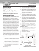
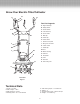
Replacement Part List

10
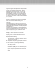
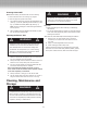
Figure 9
E
E. Power Cable J. Wing-nuts and bolts
J
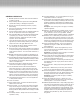
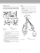
Figure 8
S
R
P
R
S
P. Driveshaft
R. Hex Bolt
S. Self-locking Nut
Q. Tines
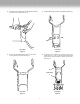
Changing the Tines
The machine is fitted with four tine wheels that can easily be
changed in pairs. Both of the tine wheel pairs can be fitted on
the left or right, as required. Always change both tine pairs at
the same time to avoid imbalance and damage to the machine.
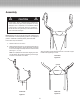
Storage
l Allow the motor to completely cool down before storing
the Tiller.
l Keep the machine clean, dry and out of the reach of
children.
l Do not cover the machine with a plastic bag. This may
cause moisture build-up.
1. Unscrew the wing-nuts (J) and fold the fork grips down.
2. Check to ensure the Power Cable (E) is not pinched.
3. Hang the machine on the frame tubing.
Q
1. Place the electric tiller on the ground. The rating label
should be facing upward.
2. Unscrew the hex bolt (R) (See Fig. 8) and the self-locking
(S) (See Fig. 8).
3. Remove the tine wheels off the driveshaft (P) (See Fig. 8).
4. Clean the driveshaft (P) with biodegradable oil.
5. Place the new tines onto the driveshaft so that the holes
on the axles line up with the holes on the driveshaft.
Import
ant! The tines must be set in the correct turning
direction. Check the
arrows on the tines and gearbox point
in the same direction.
6. Insert the hex bolt (R) through the holes and tighten on
the self-locking nut (S).