
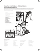
Replacement Part List


6
Unpacking
Carton Contents
• Electric garden vacuum + blower + mulcher with collection
bag attached
• Manual with registration card
1. Carefully remove the electric blower + vacuum + mulcher
and check to see that all of the above items are supplied.
2. Inspect the product carefully to make sure no breakage or
damage occurred during shipping. If you nd damaged or
missing parts, DO NOT return the unit to the store. Please
call the Snow Joe
®
+ Sun Joe
®
customer service center at
1-866-SNOWJOE (1-866-766-9563).
NOTE: Do not discard the shipping carton and packaging
material until you are ready to use the electric blower +
vacuum + mulcher. The packaging is made of recyclable
materials. Properly dispose of these materials in
accordance with local regulations.
IMPORTANT! The equipment and packaging material are not
toys. Do not let children play with plastic bags, foils or small
parts. These items can be swallowed and pose a suocation
risk!
Assembly
mWARNING! To avoid serious personal injury, read and
understand all safety instructions provided.
mWARNING! Do not connect to power supply until
assembly is complete. Failure to comply could result in
accidental starting and possible serious personal injury.
mWARNING! Before performing any maintenance, make
sure the tool is unplugged from the power supply. Failure to
heed this warning could result in serious personal injury.
mWARNING! To prevent serious personal injury, make
sure the switch is in the OFF position, the unit is unplugged
and the impeller has come to a complete stop before attaching
or removing the collection bag.
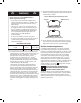
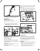
The unit arrives completely assembled with the handle set
in storage mode (Fig.1). To set the handle in working mode,
follow the instructions below.
1. Press the handle angle adjustment button, at the same
time, rotate the handle up until it locks into the working
position (Fig. 2).
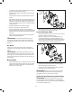
2. The handle length can be adjusted from 16 inches to
21.5 inches. To adjust the handle length, loosen the
handle lock knob by turning it counterclockwise (Fig. 3).
3. With the handle raised in the operating position, extend to
the desired height. Turn the handle lock knob clockwise to
lock the handle (Fig. 4).
Fig. 1
Fig. 2
Handle angle
adjustment button
STORAGE MODE
WORKING MODE
Fig. 3
Handle lock knob