
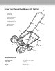
Replacement Part List
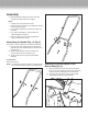
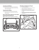


Attaching the Rear Bag (Fig. 4 & Fig. 5)
1. Assemble bag as in Fig. 4.
2. Hook bag onto steel round bar.
3. Place locking strap from the rear bag to the center bar
of the middle handle, adjust strap for proper height
so the bag does not rub the ground while mowing or
transporting. (Fig. 5).
Operation
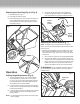
Cutting Height Adjustment (Fig. 6)
1. The cutting height of the 18” (45.7 cm) Reel Mower
can be adjusted in 9 positions from 1.63” to 2.63”
(4.1 to 6.7 cm) by moving the height adjusment levers
to the desired position. The height adjusment levers
are located next to the smaller wheels.
2. In order to set the mower to its lowest cutting position,
one at a time, pull the adjustment levers on both sides
to their highest positions.
3. In order to set the mower to its highest cutting position,
move the adjustment levers on both sides to their
lowest positions.
NOTE: The two adjustment levers MUST be set to the same
position (height).
4. The mower can be set to other cutting heights by
moving the adjustment levers to any position within
their range between the highest and lowest positions.
Adjusting the Mower Blade (Fig. 7)
NOTE: The blades were pre-adjusted prior to leaving the
factory, but it is recommended that the adjustment be veried
prior to rst use.
• Vibrations during shipping can cause misalignment, which
often causes the blades to become too loose or too tight.
This will result in a rough, uneven cut, or the mower will be
hard to push.
1. Each end of the cutting bar can be adjusted separately.
2. The cutting bar blade, which is located under the reel,
is able to pivot. The two adjustment nuts located at the
back of the mower move the cutting bar away from the
blades when they are turned counter-clockwise, and
closer to the blades when they are turned clockwise.
m WARNING: Do not overtighten adjustment screw as
this could damage cutter bar. Both screws must be tight on
nal adjustment.
Fig. 4
4
Fig. 7
Adjustment
screw
Fig. 5
Highest
cutting
position
Lowest
cutting
position
Adjustment
Level
Fig. 6