
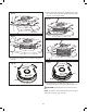
Replacement Part List
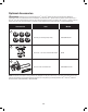


23
Assembly
mWARNING! Do not connect to power supply until
assembly is complete. Failure to comply could result in
accidental starting and possible serious personal injury.
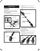
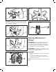
Handle Assembly
1. Clamp the auxiliary handle with the telescoping pole using
the 4 screws, as shown (Fig. 52).
Fitting the Garden Tiller
1. Insert the telescoping pole into the tiller head. Press down
on the quick-release button to lock into position (Fig. 53).
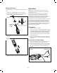
2. Insert the rear handle into the end of the telescoping
handle (Fig. 54).
3. Press down on the quick release button. Ensure the
release button snaps rmly into position to lock the handle
securely.
4. To remove, disconnect rear handle and tiller head from
ends of telescoping pole by lifting the quick release button
and pulling straight out.
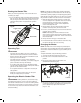
Adjusting Tiller Angle
1. Adjust the garden tiller angles by depressing the adjusting
button (Fig. 55).
2. Turn the garden tiller head to a desired angle (Fig. 55).
3. The recommended tilling angles are between 0 and 40
degrees (Fig. 55).
Garden Tiller
Fig. 52
Telescoping pole
Auxiliary
handle
Clamp
Screws
Clamp
Auxiliary
handle
Fig. 53
Telescoping pole
Tiller head
Quick-release
button
Fig. 54
Garden tiller with
telescoping pole
assembly
Quick release button
Rear
handle
Fig. 55
Adjusting
button
Tiller
head
0º
20º
40º