
User Guide

SW-120V-1L & 2L, SW-12VDC-1L & 2L
Sump Alarm High Water Alarm and Monitor
www.SumpAlarm.com
Page 1 of 4 SW-120VA12VDC-1L2L-R0616.doc
Contact: CustomerService@SumpAlarm.Com 314-787-8059
This documentation is applicable to Sump Alarm NON-WIFI part numbers starting with SW-120V-1L/XX, SW-120V-2L/XX, SW-12VDC-
1L /XX, and SW-12VDC-2L/XX.
The Sump Alarm High Water Alarm and Monitor is designed for outdoor use, sun, rain, temperature resistance, and contains only
Long Life LED Pilot lights. Your Sump Alarm carries a 3 year LIMITED warranty from the date of purchase, defined below.
Sump Alarm activates when the water level in the basin or sump rises above the desired level. The alarm system includes a red LED
beacon with integrated audible alarm buzzer.
The high level alarm system will automatically reset when the high level condition is corrected.
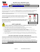
The enclosure is weatherproof to allow outdoor installation and has a flammability rating which
meets UL 94-V0. Figure 1 (at right) shows the front of the Sump Alarms to which this
documentation applies.
Read and follow all instructions and safety guidelines thoroughly before installing or operating
the system. Failure to follow the instructions could result in serious bodily injury or death
and/or property/pump damage.
SAFETY GUIDELINES
WARNING: DISCONNECT ALL POWER BEFORE INSTALLING OR SERVICING THE PUMP OR THE SUMP ALARM!
1. Read and follow all safety guidelines and installation/operation instructions.
2. Follow all national, state or provincial, and local building, plumbing and electrical codes and ordinances.
3. Do not install or operate the Sump Alarm while standing on a wet or damp surface.
4. Do not energize the head unit if an electrical component is damaged or appears damaged or the head unit is open.
5. Do not energize if there are wires disconnected or which appear loose, frayed, or damaged.
6. Be certain to close the head unit to protect other against potential electrical shock, and maintain moisture outside of the
Sump Alarm head unit.
7. Do not install the unit in locations classified as hazardous in accordance with the most recent National Electrical Code.
8. Follow all installation/operation instructions and safety guidelines accompanying the grinder pumps and/or basin system.
LOCATING & MOUNTING THE SUMP ALARM HEAD UNIT
The Sump Alarm should be mounted in a convenient location. Cable lengths need to be considered, and extra float switch cable can
be stowed above or below the water line. The head unit location should allow “line-of-sight” visibility of the indicating light from the
desired vantage point. The sound is directional, and like the light, should be pointed to a designated location.
The Sump Alarm should be securely mounted to a wall or secure vertical structure which is free of vibration. The alarm has four
mounting holes. Mounting screws have been included for your convenience. Should screws of a different length be required, utilize a
#8 Pan Head screw. A NOTE ON POWERDRILLS: WHEN MOUNTING THE FEET, PUT THE DRILL AT THE LOWEST TORQUE SETTING TO
AVOID STRIPPING THE PLASTIC RECEIVERS.
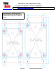
Figure 1 – 2L & 1L Head Unit