
User's Manual

Summit User’s Guide – SDC-SSD40L
9
SDC-SSD40L_UsersGuide
© 2011 – 2012 Summit Data Communications, Inc. All rights reserved.
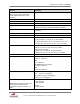
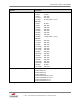
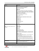
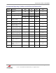
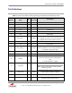
Pin Definitions
Note: In regards to GND (Ground) pins, only one must be tied down. The remaining pins identified as
GND can either be tied down or floated, depending on individual radio board design needs.
Pin
Number
Pin
Name
I/O
Voltage
Reference
Description
1
GND
-
Ground
2
GND
-
Ground
3
N/C
N/C
No Connect
4
N/C
N/C
No Connect
5
N/C
N/C
No Connect
6
N/C
N/C
No Connect
7
SYS_RST_L
I
VDDIO
Resets the radio, active low. Will be held low
for ~300nSec by a RC reset circuit when power
is applied. Do not connect when not used.
8
N/C
N/C
No Connect
9
N/C
N/C
No Connect
10
WL_GPIO_1
O
VDDIO
Wake on Wireless
Wake on Wireless is not currently supported in
the software. May be left open.
11
SDIO_SEL
I
VDDIO
SDIO Selection, hold low.
12
N/C
No Connect
13
VDDIO
-
3.3/1.8V I/O Power
This is the reference pin for all I/O signaling
pins.
It accepts 1.8VDC to 3.3VDC
14
CLK_32K
I
32k Ext Sleep Clock
Note: This pin should have a 100k pull-down
(resistor to ground).
15
SDIO_CLK
I
VDDIO
SDIO Input Clock from Host (50 MHz max)
External pull-up resistor is optional
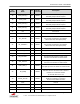
16
GND
-I
Ground
17
SDIO_DATA_0
I/O
VDDIO
SDIO Data 0 – Internal pull-up.
External pull-up resistor required