
User's Manual

Summit User’s Guide – SDC-SSD40L
18
SDC-SSD40L_UsersGuide
© 2011 – 2012 Summit Data Communications, Inc. All rights reserved.
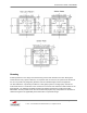
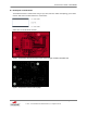
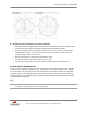
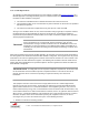
Figure 4: Bottom layer
On the bottom layer, a complete ground plane under the SSD40L is must to ensure the rf signal is
well referenced. Also, the RF trace impedance between the SDC-SSD40L (Pin 56) and the antenna
connector (J1) should be controlled within 50 ohm +/-10% and keep the trace as short as possible
(recommend less than 100 mils) to reduce the trace lose. Place 10 mils through via hole with distance
40 mil around the RF connector (J1) and beside the RF trace to avoid the possible radiation for
harmonic signal.
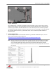
C. Antenna Specification
An external dipole antenna was tested with SSD40L to get Summit certification ID (FCC, IC, and
ETSI). Detail information will be obtained on
http://www.cisco.com/en/US/docs/wireless/antenna/installation/guide/4941.html
Note: Section 15.203 of the FCC Rules requires a unique antenna connector between the modular
transmitter and the chosen antenna. The specified antenna meets this requirement since it
uses a reverse polarity TNC connector but a length of antenna cable must be provided
between the MMCX modular transmitter connector and the reverse polarity TNC connector on
the antenna.