
User's Manual

User’s Guide – SDC-MSD40NBT
18
SDC-MSD40NBT_UsersGuide
© 2011 – 2012 Summit Data Communications, Inc. All rights reserved.
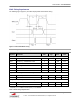
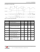
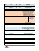
Pin
Number
Pin
Name
I/O
Voltage
Reference
Description
supported in the radio firmware.
Do not connect when not used
9
RSVD
O
VDDIO
Reserved.
Bluetooth LED Activity Indicator,
active high.
10
BT_PCM_OUT
O
VDDIO
PCM data output
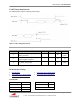
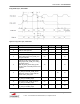
11
BT_UART_CTS_N
I
VDDIO
Clear-to-send signal for the Bluetooth
UART interface, active low.
12
RSVD
I
VDDIO
Bluetooth Device Wake-up
Signal from the host to the SDC-
MSD40NBT indicating that the host
requires attention.
Asserted – Bluetooth device must wake-up
or remain awake
Deasserted – Bluetooth device may sleep
when sleep criteria are met
The signal polarity is software configurable
and can be asserted high or low.
Note: The default is low but this is only
applicable for specific Bluetooth Sleep
mode settings. By default, the radio has
“No Sleep Mode Set”.
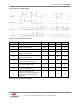
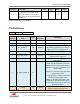
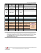
13
VCC3_3
-
3.3V Module Power
14
No Connect
Not Used. Leave Open (Float)
15
No Connect
Not Used. Leave Open (Float)
16
No Connect
Not Used. Leave Open (Float)
17
No Connect
Not Used. Leave Open (Float)
18
No Connect
Not Used. Leave Open (Float)
19
No Connect
Not Used. Leave Open (Float)
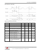
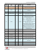
20
BT_PCM_SYNC
I/O
VDDIO
PCM sync signal
Default master (output); can be configured
slave (input)
21
No Connect
Not Used. Leave Open (Float)
22
BT_PCM_IN
I
VDDIO
PCM data input
23
No Connect
Not Used. Leave Open (Float)