RANGE HOODS SAFETY INFORMATION .................... 2 USING THE HOOD Controls ………………..……………………………….4 CARE AND CLEANING Filter ………………………………………………….. 5 Surfaces ………………………………………………. 6 Lights…………………………………………………… 6 INSTALLATION INSTRUCTIONS ....... 7 OWNER’S MANUAL & INSTALLATION INSTRUCTIONS TROUBLESHOOTING TIPS ............. 17 LIMITED WARRANTY ........................ 18 CUSTOMER SUPPORT....................
SAFETY INFORMATION IMPORTANT SAFETY INFORMATION READ ALL INSTRUCTIONS BEFORE USING WARNING TO REDUCE THE RISK OF FIRE, ELECTRIC SHOCK, OR INJURY TO PERSONS, OBSERVE THE FOLLOWING: A. Use this unit only in the manner intended by the manufacturer. If you have questions, contact the manufacturer. B. Before servicing or cleaning the unit, switch the power off at the service panel and lock the service disconnecting means to prevent power from being switched on accidentally.
REMOTE ENABLE EQUIPMENT (on some models) This device complies with part 15 of the FCC Rules. Operation is subject to the following two conditions: (1) This device may not cause harmful interference, and (2) this device must accept any interference received, including interference that may cause undesired operation. The wireless communication equipment installed on this hood has been tested and found to comply with the limits for a Class B digital device, pursuant to part 15 of the FCC Rules.
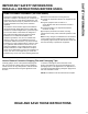
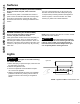
USING THE HOOD: Controls Controls On Some Models 1. Rangehood Control Panel: The control panel is located on the front of the canopy. 3. Fan Power Switch: The power switch toggles between fan settings Hi, Lo, and Off. 2. Light Switch: The light switch toggles between the lightbulb On and Off.
Filter Charcoal Filter For this model, the air needs to be recirculated through a disposable charcoal filter that helps remove smoke and odors. NOTE: DO NOT rinse or put the charcoal filter in an automatic dishwasher. The charcoal filter cannot be cleaned. It must be replaced. It is recommended that the charcoal filter be replaced every 6-12 months or if it is noticeably dirty or discolored.
CARE AND CLEANING: Surfaces / Lights Surfaces Stainless Steel Surfaces (on some models) Do not use a steel wool pad; it will scratch the surface. Use only a liquid cleanser free of grit and rub in the direction of the brush lines with a damp soft sponge. Use warm sudsy water or a stainless steel cleaner or polish to clean the stainless steel surface. Always wipe the surface in the direction of the brush line. Follow the cleaner instructions for cleaning the stainless steel surface.
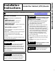
Under the Cabinet (UTC) Hoods If you have questions, call Summit at 1-718-893-3900 or visit our website at: www.summitappliance.com/support BEFORE YOU BEGIN Read these instructions completely and carefully. • IMPORTANT — Save these • IMPORTANT — Observe all governing instructions for local inspector’s use. codes and ordinances. • Note to Installer – Be sure to leave these instructions with the Customer. • Note to Customer – Keep these instructions for future reference.
INSTALLATION PREPARATION Installation Preparation DUCTWORK REQUIREMENTS WARNING TO REDUCE THE RISK OF FIRE, USE ONLY METAL DUCTWORK. NOTE: Read the ductwork sections only if you do not have existing ductwork. If you have existing ductwork, skip to the “Damage” section, and proceed. The venting system must exhaust to the outside. This hood can be vented vertically through upper cabinets or horizontally through an outside wall. Ductwork is not included.
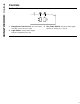
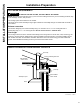
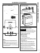
PRODUCT DIMENSIONS MOUNTING SPACE 12” 5 1⁄2” 20” X Size 24” 30” 36” *Controls may vary Bottom edge of cabinet needs to be 30” or more from the cooking surface 24″, 30″ or 36″ to match cooktop width 24" Min required 30" Max recommended to the bottom of the hood X 23 15⁄16” 29 15⁄16” 35 15⁄16” 34"-36" Typical INSTALLATION PREPARATION Installation Preparation ø 7” 3 1⁄4” 4” 7 1⁄2” PLAN THE INSTALLATION 5” CAUTION Top View 7 1⁄2” To reduce risk of fire and to properly exhaust air, be sure to
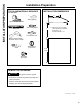
INSTALLATION PREPARATION Installation Preparation TOOLS AND MATERIALS REQUIRED (NOT INCLUDED) INSTALLATION DIMENSIONS 12" Safety glasses Pencil and tape measure Wire cutter/stripper Spirit level X X = Distance from hood to cooktop (varies depending on installation) Required Min. = 24" Recommended Max.
ADVANCE PLANNING POWER SUPPLY Vented Install Planning IMPORTANT – (please read carefully) • This hood is designed to be vented vertically using a 7" round duct or a 3 1⁄4" x 10" rectangular duct or horizontally using a 3 1⁄4" x 10" rectangular duct. • Use metal ductwork only. • Determine the exact location of the vent hood. • Plan the route for venting exhaust to the outdoors. To maximize the ventilation performance of the vent system: 1.
INSTALLATION PREPARATION Installation Preparation 1 SELECT VENT OPTION THAT YOUR INSTALLATION WILL REQUIRE (A-D) A Outside top exhaust (Vertical duct—3 1⁄4” x 10” Rectangular) 2 PREPARING MOUNTING A To install to the bottom of cabinet Use the diagram or hood as a template and mark the locations on the cabinet for the keyhole screws. Drive the 4 (F) screws partway into the bottom of the cabinet (or wood shims).
3 PREPARE FOR ELECTRICAL AND VENTING A Select the vent option that your installation will require and proceed to that section: Outside top exhaust (Vertical duct–3 1⁄4” x 10” Rectangular) • Use the diagram as a template and mark the locations on the cabinet for ductwork and electrical wiring.
INSTALLATION PREPARATION Installation Preparation 4 REMOVE ELECTRICAL KNOCKOUTS 6 REMOVE DUCT KNOCKOUT(S) FOR VENTED INSTALLATION Use a flat blade screwdriver, remove the appropriate electrical knockout from the back or the top of the hood. Determine which ducting option to use. Using a flat blade screwdriver, remove the appropriate duct knockout(s) from the top or back of the hood. 7” Round vertical discharge.
8 FOR VENTED INSTALLATIONS On Some Models: Install with vented mode deflector part. 10 MOUNT THE UTC Place the hood onto the partially installed screws using the keyholes and slide the hood back into position. 2 1 On Some Models: INSTALLATION PREPARATION Installation Instructions Install vented mode deflector part. 11 SECURE HOOD Tighten the mounting screws. Be sure the screw heads are in the narrow neck of the keyhole slot.
INSTALLATION INSTRUCTIONS Installation Instructions 12 CONNECT DUCTWORK TO HOOD (Ducted installations only) Connect ducting to hood. Use duct tape to make joints secure and airtight. 14 FINISH THE INSTALLATION On Some Models: 1. For recirculation: Install the charcoal filter. 2. For ducted installation: Install the grease filters. 13 ELECTRICAL CONNECTIONS 1. Connect the Power Supply Cable to the range hood.
You can solve many common problems easily, saving you the cost of a possible service call. Try the suggestions below to see if you can solve the problem before calling for service. Problem Possible Cause What To Do Fan/Light does not operate when either button is pressed A house fuse may be blown, or a circuit breaker tripped. Replace the fuse or reset the circuit breaker.
LIMITED WARRANTY Within the 48 contiguous United States, for one year from the date of purchase, when this appliance is operated and maintained according to instructions attached to or furnished with the product, the warrantor will pay for factory-specified parts and repair labor to correct defects in materials or workmanship. Service must be provided by a designated service company. Outside the 48 states, all parts are warranted for one year from manufacturing defects.
NOTES
An ISO 9001:2015 registered company 770 Garrison Avenue Bronx, NY 10474 TEL 718-893-3900 FAX 844-478-8799 info@summitappliance.com www.summitappliance.com 991.0701.