SUPERCHISEL 50’ - 60’ Operator’s Manual 50’ THROUGH 60’ WIDTHS SUPERCHISEL 50’ - 60’ SUPERCHISEL IMPORTANT THE OPERATOR IS RESPONSIBLE FOR ADJUSTING THE MACHINE SINCE MACHINE DOES NOT COME “FIELD READY” FROM FACTORY. CAUTION READ & UNDERSTAND OPERATOR’S MANUAL BEFORE USING MACHINE. See www.summersmfg.com for the latest version of all Summers Operator’s Manuals. SUMMERS MANUFACTURING CO., INC. WEB SITE: www.summersmfg.com MADDOCK, NORTH DAKOTA 58348....................................
Warranty Summers warrants only products of its manufacture against operational failure caused by defective materials or workmanship which occur during normal use within 12 months from the date of purchase by the end user from Summers’ dealer.
INTRODUCTION This manual provides the following information about your Summers Chisel Plow. SECTION CONTENTS Section 1 – SAFETY explains important safety precautions and familiarizes the Operator with the decals and their locations. Section 2 – ASSEMBLY includes step by step assembly instructions for your Summers Chisel Plow. Section 3 – CHISEL PLOW OPERATION provides necessary information for the operation and adjustment of the machine. Section 4 – MAINTENANCE covers recommended mechanical maintenance.
TABLE OF CONTENTS SECTION 1 – SAFETY Safety-Alert Symbol....................................................................................................................................................1-1 General Safety Practices............................................................................................................................................1-1 Safety During Transport.................................................................................................................
Maintenance for after the First Day and Week of Operation......................................................................................4-1 Daily Maintenance......................................................................................................................................................4-2 Storage.......................................................................................................................................................................
NOTES iv
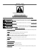
SECTION 1 - SAFETY SAFETY-ALERT SYMBOL This symbol is an alert to the potential for personal injury. This symbol means: ATTENTION! BECOME ALERT! YOUR PERSONAL SAFETY IS INVOLVED! DEFINITION OF EACH SIGNAL WORD USED IN CONJUNCTION WITH THE SAFETY-ALERT SYMBOL: DANGER indicates an imminently hazardous situation which, if not avoided, will result in death or serious injury. This signal word is limited to the most extreme hazards.
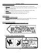
SAFETY DURING TRANSPORT SECTION 1 - SAFETY 1. ONLY TOW at a safe speed. Use caution when making corners or meeting traffic. 2. USE Safety Lights and Safety Chain between tractor drawbar and implement hitch when transporting on public roads. 3. ALWAYS use hydraulic cylinder transport locks when transporting on public roads. 4. FOLLOW ALL local laws governing transporting of farm machinery. 5. Frequently check for traffic from rear, especially during turns. SAFETY DECALS 1. KEEP SAFETY DECALS CLEAN. 2.
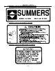
SECTION 1 - SAFETY 3. PN 8Z0202 – DECAL FOR COMPANY IDENTIFICATION 4. PN 8Z0276 – DECAL FOR GENERAL CAUTION 5.
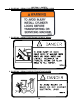
SECTION 1 - SAFETY 6. PN 8Z0342 – DECAL FOR INSTALLING CYLINDER LOCKS 7. PN 8Z0344 – DECAL FOR STAYING CLEAR OF WINGS 8.
SECTION 1 - SAFETY 9. PN 8Z0348 – DECAL FOR GAUGE WHEEL DEPTH 10. PN 8Z0800 – AMBER REFLECTOR 11. PN 8Z0805 – RED-ORANGE REFLECTOR 12. PN 8Z0810 – RED REFLECTOR SAFETY LIGHT OPERATION The Summers Safety Light Kit is equipped with a 7 pin connector which meets SAE J560 specification. To protect 7 pin connector, store in dust cap (8K8067) when not attached to towing vehicle. On most towing vehicles WITHOUT brake lights: Amber lights will turn on with flashers or turn signals.
SECTION 1 - SAFETY 1-6
SECTION 2 – ASSEMBLY INTRODUCTION GENERAL ASSEMBLY INSTRUCTIONS 1. READ AND UNDERSTAND Operator’s Manual before assembly of machine. 2. Machine should be assembled in horizontal (field) position only. 3. If machine is to be assembled INDOORS, check that exit door is a MINIMUM OF 19’6” WIDE. Minimum height requirement is Machine Width Height 28-44’ 10’8” - 18’0” 50-54’ 15’8” 56’-60’ 17’8” Shanks may be left off to reduce height and width requirement. 4.
SECTION 2 – ASSEMBLY INTRODUCTION GENERAL SAFETY PRACTICES YOU ARE RESPONSIBLE for the safe assembly of the machine. BLOCK UP ANY RAISED PART of the machine. Be sure machine is stable after blocking. DO NOT ALLOW CHILDREN or other unauthorized persons within the assembly area. ALWAYS INSPECT LIFTING CHAINS AND SLINGS for damage or wear. BE SURE LIFTING DEVICE IS RATED TO HANDLE THE WEIGHT.
SECTION 2 – SET-UP OF CENTER SECTION 1. Place front and rear center section on floor with bolt plates facing each other. 2. ATTACH sections with 24 – 3/4x2-1/4” bolts, lock washers and nuts as shown.
SECTION 2 – SET-UP OF CENTER SECTION 3. Block center frames off the floor. 4. Install cylinder attach brackets with 3/4” u-bolts. NOTE: – Rear cylinder attach brackets (8T4226) should be centered at 62” from the center of the frame. – Front cylinder attach bracket (8T4200) should be centered on the front of the frame. 5. Insert eyebolts (8K1683) into each cylinder attach bracket. – Tighten 1-1/2” nuts so the same amount of threads are above the top nut on all eyebolts.
SECTION 2 – SET-UP OF CENTER SECTION NOTE: Drawing for steps 6 through 9 is on next page. 6. All liftarms will be centered beneath cylinder attach brackets. – Use 3/4” u-bolts for 4x4 to attach liftarm pivots (8T4100) to frame. – Slide pivot pin (8T3640) through liftarm and liftarm pivots. All liftarms use the same pivot pin. – Insert 7/16 x 3-1/2” bolt in retaining bolt holes. Secure with locknut. 7. Install walking tandem assemblies to bottom of rear liftarms.
SECTION 2 – SET-UP OF CENTER SECTION 10. Attach wheels onto hubs with 5/8” wheel nuts (torque required: 170 ft-lbs). 11. Attach wing transport locks to center frame with 3/4” u-bolts. – See Detail View A for location of front transport locks. Position rear transport locks at same distance from center. – Install Transport lock pins inside storage holes of transport locks. 12. Insert 1-1/2 x 10-3/8” eyebolts into wing lift cylinder attach base.
SECTION 2 – SET-UP OF CENTER SECTION 14. Attach hitch to center with 1-1/2” x 10-5/8” pins. NOTE: Center with 1-1/2” ID 10 GA flat washers. 15. Install 7/16x3-1/2” retaining bolts through hitch pivot pins. Secure with locknuts. 16. Attach hydraulic hose holder and tip holder with 3/4 x 1-1/4” bolt and flat washer. 17. Attach hitch jack to jack spool. 18. Remove blocks from under center frame and allow wheel assemblies to support machine. Block tires to prevent movement. 19.
SECTION 2 – SET-UP PART 1 WING NOTE: It is recommended to set up both sides of machine at the same time. The left hand side will be the only one shown. 1. Attach wing to center section with pins, washers, bolts and locknuts. – Washers are used to center wing in hinges and prevent shift. 2. Fasten cylinder attach brackets (8T4226) with 3/4” u-bolts. – Bracket should be located 188” on 50’-54’, 212” on 56’-60’ from the center of the machine. 3. Insert eyebolts (8K1683) into cylinder attach bracket.
SECTION 2 – SET-UP OF PART 1 WING NOTE: Drawing for steps 4 through 8 is on next page. 4. Center liftarm under cylinder attach brackets. – Use 3/4” u-bolts for 4x4 to attach liftarm pivots (8T4100) to frame. – Slide pivot pin (8T3640) through liftarm and liftarm pivots. – Insert 7/16 x 3-1/2” bolt in retaining bolt holes. Secure with locknut. 5. Install walking tandem assembly to bottom of liftarm. – The left hand wing will use a right hand assembly – 8T4168.
SECTION 2 – SET-UP OF PART 1 WING 2-10
SECTION 2 – SET-UP OF PART 1 WING NOTE: Drawings for steps 9 through 17 is on previous page. 9. Install gauge wheel support (8T4090) onto wing with 7/8 x 2-1/2” bolts. NOTE: STEPS 10 THROUGH 14 MAY HAVE BEEN PRE-ASSEMBLED AT FACTORY 10. Apply anti-seize to jack bolt (8T6000) threads. Screw jack bolt into axle holder (8T4094) far enough to see hole on bottom of bolt through hole in axle holder. – Insert 3/16 x 2” roll pin. Insert pin far enough so it will clear tube when rotated. 11.
SECTION 2 – SET-UP OF PART 2 WING NOTE: It is recommended to set up both sides of the machine at the same time. The left hand side will be the only one shown. 1. Insert eyebolts (8K1683) into part 2 wing lift cylinder bases. – Leave eyebolts loose, they will need to be adjusted after charging hydraulic system. 2. Install four 4-1/2”x16” (8D9466) cylinders onto part 1 wings with pins provided. 3. Attach part 2 wing to part 1 wing with 8T3606 pins, 7/16” x 3-1/2” retaining bolts and locknuts.
SECTION 2 – SET-UP OF PART 2 WING NOTE: Drawing for steps 6 through 11 is on next page. 6. Center liftarm under cylinder attach brackets. – Use 3/4” u-bolts for 4x4 to attach liftarm pivots (8T4100) to frame. – The pivot closest to the center will be attached with 3/4” x 6-1/2” bolts and a trip assembly. See page 2-17 Step 2 for further information. – Slide pivot pin (8T3640) through liftarm and liftarm pivots. – Insert 7/16” x 3-1/2” bolt in retaining bolt holes. Secure with locknuts. 7.
FRONT VIEW REAR VIEW LEFT WALKING TANDEM SECTION 2 – SET-UP OF PART 2 WING 2-14
SECTION 2 – SET-UP OF PART 2 WING NOTE: Drawing for steps 12 through 21 is on previous page. 12. Attach 11L x 15 wheels onto hubs with 9/16” wheel bolts (torque required: 122 ft-lbs). NOTE: STEPS 14 THROUGH 18 MAY HAVE BEEN PRE-ASSEMBLED AT FACTORY. 13. Install gauge wheel support (8T4090) onto wing with 7/8” x 2-1/2” bolts. 14. Apply anti-seize to jack bolt (8T6000) threads. Screw jack bolt into axle holder (8T4094) far enough to see hole on bottom of bolt through hole in axle holder.
SECTION 2 – SET-UP OF PART 2 WING 22. Fasten part 2 wing rests (8T4260) with 3/4” u-bolts. – Attach supports to part 1 wing on the first and third rank. – Locate supports 161” on 50’-54’, 185” on 56’-60’ from center of the machine. – Rotate supports so wing will rest flush when folded. 24. Install optional extensions as shown in shank layout drawings on next pages.
SECTION 2 – INSTALLATION OF TRIP ASSEMBLIES 1. Hang trip assemblies according to layout. NOTE: Installation of trip assemblies can be done after machine is raised. Complete hydraulic assembly on pages 2-19 through 2-30 before mounting trip assemblies if preferred. – Use 3/4” u-bolts for 4x4 tube with 3/4” lock washers and 3/4” nuts. – Tighten u-bolts an equal amount on top and bottom. The same amount of threads should appear on top and bottom of the u-bolt. 2.
SECTION 2 – INSTALLATION OF TRIP ASSEMBLIES 2-18
SECTION 2 – HYDRAULIC SET-UP OF DEPTH CONTROL CIRCUIT NOTE: The Summers Superchisel uses rephasing hydraulic depth control cylinders. Oil from the rod end of largest cylinder travels to the base end of second cylinder and so forth. It is very important that all hoses are routed correctly or machine will not operate properly. Helpful Hint: Leave rubber backed clamps and plastic clamps loose at locations where depth control hoses will use the same bolts as wing lift hoses.
SECTION 2 – HYDRAULIC SET-UP OF DEPTH CONTROL CIRCUIT – Pull hose tight between points 2 and 3. This will prevent hose from laying in the way of the transport lock when wing is folded. – Hose must go from the rod end (bottom) of the 5 x 10” to the base end (top) of the 4-1/2 x 10”. 5. Route 1/2” hose from the 4-1/2 x 10” to the 4 x 10”. – Leave slack between points 4 and 5 to keep hose from stretching during folding and field operation.
SECTION 2 – HYDRAULIC SET-UP OF DEPTH CONTROL CIRCUIT FOR 50’ TO 54’ CHISEL 2-21
SECTION 2 – HYDRAULIC SET-UP OF DEPTH CONTROL CIRCUIT FOR 56’ TO 60’ CHISEL 2-22
SECTION 2 – HYDRAULIC SET-UP OF WING LIFT CIRCUIT FOR 50’ TO 54’ CHISEL 2-23
SECTION 2 – HYDRAULIC SET-UP OF WING LIFT CIRCUIT FOR 56’ TO 60’ CHISEL 2-24
SECTION 2 – HYDRAULIC SET-UP OF WING LIFT CIRCUIT Note: The Summers Superchisel uses in-line restrictors to control hydraulic flow of the part 2 wing lift cylinders and extension (lowering) of the part 1 wing lift cylinders. It is important that restrictors are installed in the wing lift circuit. This chisel plow uses sequencing valves to insure the wings fold properly. After installation, it may be necessary to change the pressure level of these valves for the wings to fold properly.
SECTION 2 – HYDRAULIC SET-UP OF WING LIFT CIRCUIT 4. Retraction of part 1 wing lift cylinders is controlled with a sequencing valve. This step will show proper plumbing for this part of the wing lift circuit. – Connect an 18” hose from the left hand end of the manifold block to port #1 on the left hand sequencing valve. – Connect another 18” hose from the middle port on the right hand side of the manifold block to port #3 on the left sequencing valve. This hose will allow draining of the valve.
SECTION 2 – HYDRAULIC SET-UP OF WING LIFT CIRCUIT 6. Extension of part 2 wing lift cylinders is controlled with a sequencing valve. This step will show proper plumbing for this part of the wing lift circuit. – Connect an 18” hose from the right hand end of the manifold block to port #1 on the right hand sequencing valve. – Connect another 18” hose from the middle port on the left hand side of the manifold block to port #3 on the sequencing valve. This hose will allow draining of the valve.
SECTION 2 – CONNECTING AND SEQUENCING WING LIFT 1. Charge wing lift cylinder system. – Block rod end of cylinders up so that cylinder shafts can be extended without hitting anything. – Fully cycle cylinders several times to make sure that all air has been removed from the system. – Leave cylinders in fully extended position. 2. Connect rod end of 5 x 36” cylinders to part 1 wing. – Install wing lift pin, rollers and washers onto the wing and cylinder rod tube. Secure pin with 8T3810 washer and roll pin.
SECTION 2 – CONNECTING AND SEQUENCING WING LIFT 3. Connect rod end of 4-1/2 x 16” cylinders to part 2 wing. – Install one 8T3608 pin with 5/16” roll pin and 1-1/2” FW into an 8T3590 link and insert it into the collar on the part 1 wing. Install another 8T3590 link onto the other side of pin and secure with 1-1/2” FW (as required to remove clearance, must be free to pivot) and 5/16” roll pin. – Install an 8T3608 pin with 5/16” roll pin and 1-1/2” FW into the opposite end of the 8T3590 link.
SECTION 2 – CONNECTING AND SEQUENCING WING LIFT 4. Before raising outer wings for the first time, make sure wing lift cylinder attach eyebolts are loose. – Slowly raise part 2 wings into transport position. – Fully retract part 2 cylinders and let wings rest against transport supports. Test adjustment of sequencing valve before turning set screw. If valve is set with too much pressure, part 1 wings will not rise. To reduce the amount of pressure, turn set screw outward.
SECTION 2 – DECALS/SAFETY LIGHT KIT/OPTIONS 1. Install danger, warning and caution decals. – Part numbers can be found on the lower right hand corner of each decal. Match this number with decal location drawing on Page 1-6. – The drawing gives approximate locations of decals. Decals must be clearly visible. – Order replacement decals if any are damaged. 2. Install reflectors. – Attach Amber reflectors (8Z0800) on front corners and sides of machine in transport position.
NOTES 2-32
SECTION 3 – CHISEL PLOW OPERATION CHISEL PLOW OPERATION SAFETY 1. READ AND UNDERSTAND Operator’s Manual before using machine. Review at least annually thereafter. 2. VERIFY that all safety devices and shields are in place before using machine. 3. KEEP hands, feet, hair and clothing away from moving parts. 4. STOP engine, place all controls in neutral, set parking brake, remove ignition key and wait for all moving parts to stop before servicing, adjusting, maintaining or unplugging. 5.
SECTION 3 – CHISEL PLOW OPERATION INITIAL HOOKUP 1. Make tractor to hitch connection with locking draw pin and safety chain. 2. Retract jack and rotate into storage position. Connect Safety Light Kit to 7 pin receptacle. 3. Plug wing lift hoses into desired tractor outlet. Insure that tips and couplers are CLEAN. 4. Plug depth control hoses into desired tractor outlet. 5. Park tractor and chisel plow on a level surface. 6. Remove transport lock pins on wings. 7. Lower the wings with caution.
SECTION 3 – CHISEL PLOW OPERATION 7. Continued: SEQUENCING VALVE OPERATION – Make sure the part 1 wing lift cylinders are fully extended before the part 2 wings start to move. If part 2 wings move, sequencing valve pressure for base end of the 4-1/2 x 16” cylinders must be increased. To increase the sequencing valve pressure, loosen the jam nut on the valve (valve is located at the RH side of the center section on the 2nd rank).
SECTION 3 – CHISEL PLOW OPERATION 8. Fully extend depth control cylinders and maintain hydraulic pressure for 30 seconds to insure that all air has been purged from the system. NOTE: This machine has rephasing style depth control cylinders. When cylinders are fully extended, oil will bypass through a rephasing slot on each cylinder in order to equalize the system. 9. Remove depth control cylinder transport locks.
SECTION 3 – CHISEL PLOW OPERATION 9. (Continued) – Store transport locks in their appropriate holders. 10. Become familiar with single point depth control. Control can be found on 6 x 10 cylinder located on the center section. A hairpin clip is used to hold plunger in desired location.
SECTION 3 – CHISEL PLOW OPERATION FIELD OPERATION 1. Always rephase cylinders before starting field operation. 2. Choose a flat spot in a field to set depth and level the chisel plow. IMPORTANT! The operator is responsible for adjusting the machine since machine does not come “Field Ready” from the factory. 3. Determine desired tillage depth by working test strips within the field.
SECTION 3 – CHISEL PLOW OPERATION 3. (Continued) – Trip Assembly Limit NOTE: Increased draft will occur if connecting bolt continually rides above the trip assembly cap. This will consume horsepower as well as reduce the life of the trip assembly. 4. After determining desired tillage depth, set depth control plunger accordingly. Standard plunger hole spacing gives 5/16” cylinder stroke adjustment. By rotating plunger 90 degrees, a half step adjustment can be achieved.
SECTION 3 – CHISEL PLOW OPERATION 5. Leveling the chisel plow from side to side. Stop the tractor with the machine still in the ground. Check the depth of tillage on the left wing, center, and right wing. If leveling is necessary, use wrenches provided to adjust the eyebolts on the cylinder attachments located at the rear of the machine. *NOTE: Insure that cylinder attach holes are aligned when eyebolts are tightened. IMPORTANT! Pressure must be removed from cylinders before adjusting eyebolts.
SECTION 3 – CHISEL PLOW OPERATION NOTE: It is best to check levelness of the chisel plow after each adjustment by working test strips within the field. 6. Leveling the machine from front to back. Check depth of tillage at front and back of the machine. If leveling is necessary, use wrenches provided to adjust the eyebolt on the front wheel assembly up or down. The front center lift arm has two cylinder attach locations.
SECTION 3 – CHISEL PLOW OPERATION 7. Setting gauge wheels. After depth has been established and chisel plow has been leveled, operator must set gauge wheels. Stop tractor with chisel plow in the ground. Adjust crank assembly until wheel rests on top of the ground. Set bolts are installed on each gauge wheel assembly. Adjust set bolts so gauge wheel depth can still be changed but rotation of assembly is limited. If running at a consistent depth, set bolts can be securely tightened to lock gauge wheels.
SECTION 3 – CHISEL PLOW OPERATION 8. Operation “Tips” – The 7 solid lift arms on this machine are designed to prevent skewing from side to side. To avoid damage to the lift arms and wheel assemblies, do not take sharp corners with the chisel plow in the ground. – Floating hitch machines are designed to follow contours of the ground. The Summers chisel plow has a short wheel base in field position that allows it to smoothly follow through ditches and gullies.
SECTION 3 – CHISEL PLOW OPERATION 4. Use a safety chain between tractor drawbar and chisel plow hitch when transporting. 5. Only tow at a safe speed – 20 MPH MAXIMUM. Use caution when making corners or meeting traffic. 6. Follow all local laws governing transporting of farm machinery. 7. Be aware of and comply with all height and width transport requirements. (See specifications page 5-2). 8. Stay clear of overhead lines. 9. Frequently check for traffic from rear, especially during turns. 10.
SECTION 4 – MAINTENANCE MAINTENANCE SAFETY 1. STOP engine, place all controls in neutral, set parking brake, remove ignition key and wait for all moving parts to stop before servicing, adjusting or maintaining. 2. BE CAREFUL when working around high pressure hydraulic system. 3. ALWAYS make sure that pressure is relieved from hydraulic circuits before servicing or disconnecting from tractor. 4. USE EXTREME CARE when making adjustments. 5. KEEP CHILDREN AWAY from machinery at all times. 6.
SECTION 4 – MAINTENANCE DAILY MAINTENANCE 1. Grease lift arms, walking tandem assemblies, wing pivots, and hitch pivots. 2. Check all hydraulic components for leaks. 3. Check the tightness of all wheel bolts. PERIODIC MAINTENANCE 1. Repack wheel bearings and check their tightness (See Page 6-10). 2. Check tire air pressure (See specification page 5-2). 3. Check tightness of trip assembly hardware as explained under “Maintenance for after the first day and week of operation”. 4.
SECTION 5 – TROUBLESHOOTING PROBLEM CAUSE A. Depth control cylinders out of phase. B. Eyebolts not adjusted properly. 1. Not tilling level. C. Gauge wheels not adjusted properly. D. Hard soils conditions. 2. Not pulling straight. A. Chisel plow not tilling level. A. Excessive travel speed. B. Hard soil conditions. 3. Inconsistent tillage depth. C. Deep furrows. A. Working in extremely heavy trash. 4. Plugging. 5. Poor penetration. 6. Depth control cylinders not working properly. B.
SECTION 5 – SPECIFICATIONS WIDTH, HEIGHT, WEIGHT, LENGTH SIZE APPROX. TRANSPORT WIDTH APPROX TRANSPORT STANDARD HEIGHT WEIGHT WEIGHT W/3BAR 104 HARROWS LENGTH W/3BAR 104 HARROWS 50’ 19’2” 15’8” 21,896 23,809 33’ 52’ 19’2” 15’8” 22,190 24,140 33’ 54’ 19’2” 15’8” 22,670 24,674 33’ 56’ 19’2” 17’8” 26,302* 26,302* 33’ 58’ 19’2” 17’8” 26,836* 26,836* 33’ 60’ 19’2” 17’8” 27,401* 27,401* 33’ * Available with Mounted Harrows Only.
SECTION 6 – PARTS BRING OWNER REGISTER INFORMATION LOCATED AT THE BEGINNING OF THIS MANUAL WHEN ORDERING PARTS (SERIAL NUMBER IS LOCATED BY THE HITCH PIECE).
SECTION 6 – PARTS 6-2
SECTION 6 – PARTS 6-3
SECTION 6 – PARTS 6-4
SECTION 6 – PARTS 6-5
SECTION 6 – PARTS 6-6
SECTION 6 – PARTS 6-7
SECTION 6 – PARTS 6-8
SECTION 6 – PARTS 6-9
SECTION 6 – PARTS TRIP ASSEMBLY 8T3200 (200 FT-LBS) 8X0316 8X0327 8X0106 8X0261 (100 FT-LBS) 8T5200 8T0600 700# BLACK 8T0602 1000# GREEN 8X0260 8T5020 8X0278 8X0115B 8X0306 8T5000 8T6810 8T3300 8T0100 8T5150 8R6805 8X0264 8T5050 8K5515 8T0500 STD 8T0504 +3" 8X0118 8X0306 8X0316 AVAILABLE ATTACHMENTS: 8K6938 - SWEEP 14" 50° 1/2"BLT 2.25C-C 8K6940 - SWEEP 16" 50° 1/2"BLT 2.25C-C 8K6942 - SPIKE REVERSIBLE 4.
SECTION 6 – PARTS 1. Attach hitch frame to rear of chisel plow. – Use 3/4 x 2” bolts. 2. Slide rear hitch slide into place. 3. Insert spring load pin. – Spring and washer will be held in place by hitch channel and 3/16” cotter pin. 4. Install rear hitch swivel. – Use pin and cotter keys provided. 5. Install Support Cable between hitch and front center section.
HUB AND AXLE COMPONENTS Assembly Notes: A. Before towing machine, pack wheel bearings and fill 1/2 of hub cavity with high quality bearing grease. B. Tighten axle nut to 45 ft.-lbs, loosen nut until first slot is aligned with hole in axle, install cotter pin and bend to retain. Legend: SMC Part Number INDUSTRY Part Number or Size H413 H511 H517 H611 H614 HD812 1. SEAL 2. INNER BEARING 3. INNER RACE 4. OUTER 5.
SECTION 6 – PARTS 6-13
SECTION 6 – PARTS 1. 52” mounting arms (PN 8H2314) should be used when attaching Summers mounted harrows. 2. Mounting arm location can be found on the following layout drawings. – In certain locations, the mounting arm will be installed directly behind a liftarm pivot. A spacer block has been welded to the chisel plow frame so there is no interference between u-bolts and the mounting head.
SECTION 6 – PARTS 6-15
SECTION 6 – PARTS 6-16
SECTION 6 – PARTS 6-17
SECTION 6 – PARTS 6-18
SECTION 6 – PARTS 6-19
8X0260 3/4" N 8X0355 8X0044 7/16" X 3-1/2" 8X0306 3/4" LW 8K5515 3/4 X 4 X 6" 8X0234 7/16" LNUT 8K1640 8T4000 40' - 60' (SHOWN) 8CC4000 28' - 38' REMOVE HITCH AS SHOWN 5/22/2012 9T6012.
SEE NOTE 8X0242 NY-LOCK 1/2" N 8X0072 1/2" X 3-3/4" 8K7042 8K1105S REMOVE HIGHLIGHTED COMPONENTS. REMOVE WHEEL/TIRE AND HUB FROM WALKING TANDEM. THESE PARTS WILL BE RE-USED NOTE: LIMIT CABLE ONLY USED ON 40' - 44' WITH REAR HITCH, AND ALL 50' - 60' MACHINES. 5/22/2012 9T6012.
8X0285 1 1/2" N 8X0315 1-1/2" LW 8T3950 8X0155 1.5" X 9" 5/22/2012 9T6012.
A 8X0307 7/8" LW 8X0130 7/8" X 2" DETAIL A SCALE 1 / 10 8T3955 8X0132 7/8" X 2-1/2" 7CC0510 8X0307 7/8" LW 8X0268 7/8" N 5/22/2012 9T6012.
8L0246 8CC6026 8X0268 7/8" N 8X0307 7/8" LW 8X0133 7/8 X 3" 8CC6022 8X0044 7/16" X 3-1/2" 8T3620 8CC6000 8X0234 7/16" LNUT 5/22/2012 9T6012.
8X0292 2" SLTD N 8X0320 3/8" FW 8X0015 3/8" X 3 3/4" 8X0320 3/8" FW 8X0202 3/8" LN 8K5200 8L0320 7L2150 7P8530 8X0261 3/4" LN 8L0320 8K7042 8CC6030 8X0072 1/2" X 3-3/4" 8X0122 3/4 X 4 1/2" 8K1105S 8CC6035 8X0311 1 1/4" LW 8X0284 1 1/4" N 8X0242 NY-LOCK 1/2" N 5/22/2012 9T6012.
8X0111 3/4" X 2-1/2" 8X0306 3/4" LW 8X0318 3/4" FW 8D9108 1/4 X 2" RP 8X0285 1 1/2" N 8K9106 8CC6028 8K9106 5/22/2012 9T6012.
SINGLE POINT DEPTH CONTROL USED ON 5-SECTION (50' - 60') CHISEL PLOWS ONLY. A 8T3300 8X0000B 1/4" X 1" 8T1010 POPPET 8X0523 ROLL PIN 8T3300 8T6810 8X0328H 7CC0385 7CC0385 8CC0780 8T6810 8CC0755 8X0223 1/4" FN 8CC0790 8T6810 8X0316 1" FW 8X0316 1" FW 8X0282 8CC0750 8X0282 1 /2 8CC0785 " SEE NOTE DETAIL A SCALE 1 / 10 8CC0740 NOTE: WELD BOTH SIDES OF TAB TO TUBE. TABS SHOULD BE LOCATED 1/2" BACK FROM FRONT FACE OF TUBE, AS SHOWN. BEAD SIZE = 1/4" 5/22/2012 9T6012.
8X0355 8X0044 7/16" X 3-1/2" 8X0234 7/16" LNUT 8K1640 8T4000 40' - 60' (SHOWN) 8CC4000 28' - 38' 4/26/2012 9T6012.
SEE NOTE NOTE: WELD BOTTOM OF BOLT PLATE TO TUBE AS SHOWN. BEAD SIZE = 3/4". DO NOT WELD ACROSS FACE OF TUBE. 4/26/2012 9T6012.
28'-44' CHISEL CASTER HYD.
8N4216 1/2 X 216" + 8J5110 UNION + 8J4216 1/2 X 216" 50'-60' CHISEL CASTER HYD. 8J6020 3/4"-16ORB X 10 JIC(M) 90° ADP 8N4228 1/2 X 228" 8N4216 1/2 X 216" 8T1037 3.5 X 10" CYL 8T1040B 4.0 X 10" CYL 8T1045 4.5 X 10" CYL 56'-60' ADD 8J5110 UNION + 8N4060 1/2 X 60" 8J6020 3/4"-16ORB X 10 JIC(M) 90° ADP 8N4216 1/2 X 216" 8J5690 3/4-16X3/4-16 ORB M-SW 90° UNION 8J5312 #10(M) X #10(M) X 3/4ORB TEE PORT 3 8J7108 8T1050 5.
SECTION 6 – PARTS Stock Code 8A1155 8A1156 8A1157 8A4044 8A4048 8A4050 8A4052 8C1720 8C1740 8C1750 8C1755 8C1760 8D0350 8D2440 8D2460 8D2470 8D3035 8D3130 8D3140 8D3150 8D3152 8D5312 8D5315 8D5319 8D5332 8D8490 8D8500 8D8521 8D8522 8D9108 8D9466 8D9468 8G8010 8G8018 8G8020 8G8022 8H1306 8H1311 8H1320 8H1325 8H1498 8H1499 8H1504 8H1506 8H1510 8H1520 8H1522 8H1530 8H1532 8H2010 8H2100 8H2120 8H2144 8H2190 8H2315 8HD0080 Description U-BOLT 3/8 X 6-1/16 X5”SQ U-BOLT 3/8 X4-1/16 X5” SQ U-BOLT 3/8 X 4-1/16 X 7”
SECTION 6 – PARTS 8K7130 8K7132 8K7150 8K7150S 8K8000 8K8010 8K8020 8K8060 8K8067 8K8068 8K8070 8K8072 8K8075 8K8077 8K8080 8K8088 8K8090 8K8092 8K8094 8K8095 8K8096 8K8200 8K8210 8K9106 8K9174 8K9176 8K9178 8K9180 8K9640 8K9650 8L0252 8L0256 8L0258 8L0260 8L0262 8L0266 8N3018 8N3028 8N3035 8N3048 8N3060 8N3070 8N3084 8N3096 8N3124 8N3136 8N3150 8N3156 8N3160 8N3180 8N3204 8N3216 8N3228 8N3252 8N3288 8N3312 RACE INNER FOR HD812 LM3720 RACE OUTER FOR HD812 LM2720 AXLE HD812 2-1/2”DIA X11-1/2” AXLE HD812 X 1
SECTION 6 – PARTS 8T1037 8T1040 8T1040B 8T1045 8T1050 8T1055 8T1060 8T1135 8T1137 8T1140 8T1140B 8T1145 8T1150 8T1155 8T1160 8T2510 8T2514 8T2520 8T2530 8T2986 8T2988 8T2990 8T3100 8T3200 8T3300 8T3400 8T3590 8T3600 8T3606 8T3608 8T3620 8T3625 8T3640 8T3800 8T3810 8T3820 8T4000 8T4020 8T4030 8T4032 8T4040 8T4042 8T4046 8T4048 8T4050 8T4052 8T4054 8T4056 8T4058 8T4059 8T4060 8T4070 8T4072 8T4074 8T4076 8T4080 HYD CYL 3.75 X 10”R3755M-10BP HYD CYL 4.0 X 10” REPHASE 96HYD CYL 4.0 X10” FOR 5PLX 99HYD CYL 4.
SECTION 6 – PARTS 8X0008B 8X0010 8X0011 8X0013 8X0014 8X0015 8X0016 8X0021 8X0021A 8X0021B 8X0022 8X0023 8X0030 8X0031 8X0033 8X0034 8X0036 8X0037 8X0038 8X0041 8X0044 8X0045 8X0046 8X0047 8X0048 8X0061 8X0062 8X0063 8X0064 8X0065 8X0066 8X0066S 8X0067 8X0068 8X0069 8X0070 8X0072 8X0073 8X0074 8X0075 8X0077 8X0080 8X0083 8X0084 8X0087 8X0090 8X0091 8X0092 8X0093 8X0095 8X0096 8X0098 8X0099 8X0101 8X0102 8X0106 BOLT 3/8-16X 2”FULLTHD GR5 PLN BOLT 1/4-20NC X 1-1/4” GR5 ZDI SCREW RD HD SLOT1/4-20X1.
SECTION 6 – PARTS 8X0262 8X0264 8X0265 8X0267 8X0269 8X0270 8X0277 8X0278 8X0280 8X0281 8X0282 8X0283 8X0284 8X0285 8X0286 8X0287 8X0289 8X0290 8X0292S 8X0300 8X0301 8X0302 8X0303 8X0304 8X0306 8X0307 8X0308 8X0309 8X0312 8X0313 8X0314 8X0316 8X0317 8X0318 8X0319 8X0320 8X0322 8X0323 8X0324 8X0325 8X0326 8X0327 8X0328 8X0329 8X0332 8X0341 8X0355 8X0361 NUT TOP LOCK 3/4”-10NC GR2 PLN BEVEL NUT CNTR LOCK3/4”-10 ZDI NUT CNTR LOCK3/4”-10NC GR2 ZDI NUT HEX 7/8”-9NC GR2 PLN NUT JAM 7/8”-9NC GR2 ZDI NUT CENTR LOC
History of Summers Manufacturing Co., Inc. 1965 – Summers Manufacturing is founded by Harley Summers, who purchases patent rights for Goebel truck and pickup hoists from the Goebel Brothers of Lehr, ND. These hoists, produced in Harley Summers’ blacksmith shop the first year, were distributed nationwide by a Cincinnati, Ohio, dealer. With increasing sales, the company soon outgrows the small shop. Summers wins the Herman harrow contract, beginning the company’s Herman culti-harrow line.
Model 700 Rock Picker Superrollers Superchisel Coulter-Chisel Disk-Chisel Hydraulic Fold Coil Packer & Hydraulic Fold Rolling Chopper Mounted Harrows Rolling Choppers Superharrow Plus & Superharrow 2650 Diamond Disk & 2510 DT Supercoulter Plus © Copyright 2013 Summers Manufacturing Co., Inc.