SUPERCHISEL 16’-44’ Operator’s Manual 16’ THROUGH 44’ WIDTHS SUPERCHISEL 16’-44’ SUPERCHISEL IMPORTANT THE OPERATOR IS RESPONSIBLE FOR ADJUSTING THE MACHINE SINCE MACHINE DOES NOT COME “FIELD READY” FROM FACTORY. CAUTION READ & UNDERSTAND OPERATOR’S MANUAL BEFORE USING MACHINE. See www.summersmfg.com for the latest version of all Summers Operator’s Manuals. SUMMERS MANUFACTURING CO., INC. WEB SITE: www.summersmfg.com MADDOCK, NORTH DAKOTA 58348....................................
Warranty Summers warrants only products of its manufacture against operational failure caused by defective materials or workmanship which occur during normal use within 12 months from the date of purchase by the end user from Summers’ dealer.
INTRODUCTION This manual provides the following information about your Summers Chisel Plow. SECTION CONTENTS Section 1 – SAFETY explains important safety precautions and familiarizes the Operator with the decals and their locations. Section 2 – ASSEMBLY includes step by step assembly instructions for your Summers Chisel Plow. Section 3 – CHISEL PLOW OPERATION provides necessary information for the operation and adjustment of the machine. Section 4 – MAINTENANCE covers recommended mechanical maintenance.
TABLE OF CONTENTS SECTION 1 – SAFETY Safety-Alert Symbol.............................................................................................................................................. 1-1 General Safety Practices...................................................................................................................................... 1-1 Safety During Transport...........................................................................................................................
SECTION 5 – TROUBLESHOOTING AND SPECIFICATIONS .......................................................................... 5-1 Width, Height, Weight........................................................................................................................................... 5-2 Tire Specifications................................................................................................................................................ 5-2 Proper Bolt Use......................................
NOTES iv
SECTION 1 - SAFETY SAFETY-ALERT SYMBOL This symbol is used to denote possible danger and care should be taken to prevent bodily injury. This symbol means: ATTENTION! BECOME ALERT! YOUR SAFETY IS INVOLVED! Definition of each Signal Word used in conjunction with the Safety-Alert symbol. DANGER indicates an imminently hazardous situation which, if not avoided, will result in death or serious injury. This signal word is to limited to the most extreme situations.
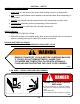
SAFETY DURING TRANSPORT SECTION 1 - SAFETY 1. ONLY TOW at a safe speed. Use caution when making corners or meeting traffic. 2. USE a safety chain between tractor drawbar and implement hitch when transporting on public roads. 3. ALWAYS use hydraulic cylinder transport locks when transporting on public roads. 4. FOLLOW ALL local laws governing transporting of farm machinery. 5. Frequently check for traffic from rear, especially during turns. SAFETY DECALS 1. KEEP SAFETY DECALS CLEAN. 2.
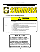
SECTION 1 - SAFETY 3. PN 8Z0202 (3.5”) & 8Z0204 (5.5)” – DECAL FOR COMPANY IDENTIFICATION ® 4. PN 8Z0276 – DECAL FOR GENERAL CAUTION CAUTION 1. Read and understand Operator’s Manual before using machine. 2. For Sprayers: a. Read and follow chemical manufacturers’ WARNINGS, instructions and procedures before using. b. Use recommended personal protective equipment to reduce or eliminate chemical contact. c. Never run pump dry. 3. Verify all safety devices and shields are in place before using machine. 4.
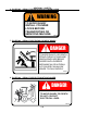
SECTION 1 - SAFETY 6. PN 8Z0342 – DECAL FOR INSTALLING CYLINDER LOCKS WARNING TO AVOID INJURY INSTALL CYLINDER LOCKS BEFORE TRANSPORTING OR SERVICING MACHINE. 8Z0342 7. PN 8Z0344 – DECAL FOR STAYING CLEAR OF WINGS DANGER TO AVOID INJURY OR DEATH STAND CLEAR OF MACHINE WHEN WINGS ARE BEING RAISED AND LOWERED. MECHANICAL OR HYDRAULIC FAILURE CAN ALLOW WINGS TO FALL RAPIDLY. 8Z0344 8. PN 8Z0346 – DECAL FOR ELECTROCUTION DANGER DANGER TO AVOID INJURY OR DEATH DO NOT CONTACT ELECTRICAL LINES.
SECTION 1 - SAFETY 9. PN 8Z0348 – DECAL FOR GAUGE WHEEL DEPTH 10. PN 8Z0800 – AMBER REFLECTOR 11. PN 8Z0805 – RED-ORANGE REFLECTOR 12. PN 8Z0810 – RED REFLECTOR SAFETY LIGHT OPERATION The Summers Safety Light Kit is equipped with a 7 pin connector which meets SAE J560 specification. To protect 7 pin connector, store in dust cap (8K8067) when not attached to towing vehicle. On most towing vehicles WITHOUT brake lights: Amber lights will turn on with flashers or turn signals.
SECTION 1 - SAFETY 1-6
SECTION 2 – ASSEMBLY INTRODUCTION GENERAL ASSEMBLY SAFETY PRACTICES 1. READ AND UNDERSTAND Operator’s Manual before assembly of machine. 2. Machine should be assembled in a horizontal (field) position only. 3. If machine is to be assembled INDOORS, check that exit door is a MINIMUM OF 20’6” WIDE. Height requirement varies from 10’8” to 18’0”. Shanks may be left off to reduce height and width requirement. 4. Reference to “RIGHT” and “LEFT” is determined when machine IS VIEWED FROM THE REAR. 5.
SECTION 2 – ASSEMBLY INTRODUCTION GENERAL SAFETY PRACTICES YOU ARE RESPONSIBLE for the safe assembly of the machine. BLOCK UP ANY RAISED PART of the machine. Be sure machine is stable after blocking. DO NOT ALLOW CHILDREN or other unauthorized persons within the assembly area. ALWAYS INSPECT LIFTING CHAINS AND SLINGS for damage or wear. BE SURE LIFTING DEVICE IS RATED TO HANDLE THE WEIGHT.
SECTION 2 – SET-UP OF CENTER SECTION (16’-20’) 1. Place front and rear center section on floor with bolt plates facing each other. 9T2012H.iam/CENTER 2/15/2011 8CC5230 8X0260 3/4" N 8X0306 3/4" LW 8CC5018 16' & 20' CENTER 8T4015 8K5515 3/4 X 4 X 6" 8X0112 3/4X2-1/4" 8X0306 3/4" LW 8X0260 3/4" N 8T4030 - 16' REAR 8CC4028 - 20' REAR (SHOWN) 2. ATTACH sections with 48 – 3/4x2-1/4” bolts, lock washers and nuts as shown.
8K5515 3/4 X 4-1/16 X 6" 8X0260 3/4" N 8X0286 1 1/2" JN 8X0285 1 1/2" N 8T4224 q 2-4 8D9108 8K9106 8T1060 8CC4000 8X0044 7/16" X 3-1/2" 8K1640 8X0234 7/16" LNUT 8X0044 7/16" X 3-1/2" 8A1156 3/8 X 4-1/16 X 5" 8T4166 8T4190 8X0044 7/16" X 3-1/2" 8X0072 1/2" X 3-3/4" 8T3640 8T4101 8K1100 8X0234 7/16" LNUT 8T3620 8CC4140 8X0203 3/8" FN 8X0242 NY-LOCK 1/2" N 8R6914 8K7033 11L LRF 3/19/2014 9T2012H/CENTER W-CYL.
SECTION 2 – SET-UP OF CENTER SECTION (16’-20’) 3. Block center frames off the floor. 4. Install cylinder attach brackets with 3/4” u-bolts. NOTE: – Locate Rear Cylinder Attach Brackets (8T4224) 62” from frame center. 5. Insert eyebolts (8K1755) into each cylinder attach bracket. – Tighten 1-1/2” nuts so the same amount of threads are above top nut on all eyebolts. Insure that cylinder attach holes are aligned when eyebolts are tightened. NOTE: Drawing for steps 6 through 10 is on previous page. 6.
L 78" R 65 1/2" L 53" R 42" 30" R L 18" 6" 2-6 R 0" L 6" R 18" 30" L L 42" R 53" 65 1/2" L R 78" 90" R 11/30/2010 9T1612H.
L 114" R 90" L 78" R 65 1/2" L 53" R 42" R L 18" 6" 2-7 R 0" L 6" R 18" 30" L L 42" R 53" 65 1/2" L R 78" 90" 102" L L R 114" 11/30/2010 9T2012H.
SECTION 2 – SET-UP OF CENTER SECTION (24’-30’ NARROW) 1. Place front and rear center section on floor with bolt plates facing each other. 2. ATTACH sections with 48 – 3/4x2-1/4” bolts, lock washers and nuts as shown. 8CC5230 8T4010 8CC5062 8K5515 3/4 X 4 X 6" 8X0260 3/4" N 8X0112 3/4X2-1/4" 24', 26', 28' & 30' NARROW CENTER 8X0306 3/4" LW 2/16/2011 8X0306 3/4" LW 8CC5070 8X0260 3/4" N 9T2412N.iam/CENTERS 3. Block center frames off the floor.
SECTION 2 – SET-UP OF CENTER SECTION (24’-30’ NARROW) 4. Install cylinder attach brackets with 3/4” u-bolts. NOTE: – Locate Rear Cylinder Attach Brackets (8T4224) 66” from frame center. 5. Insert eyebolts (8K1755) into each cylinder attach bracket. 2-9 9T2412N.iam/CENTER W-CYL.
SECTION 2 – SET-UP OF CENTER SECTION (24’-30’ NARROW) NOTE: Drawing for steps 6 through 10 is on next page. 6. All liftarms will be centered beneath cylinder attach brackets. – Use 3/4” u-bolts for 4x4 to attach liftarm pivots (8T4100) to frame. – Slide pivot pin (8T3640) through liftarm and liftarm pivots. – Insert 7/16 x 3-1/2” bolt in retaining bolts holes. Secure with lock nut. 7. Install walking tandem assemblies to bottom of liftarms.
8CC4325 24', 26', 28' & 30' NARROW 8X0260 3/4" N 8T1050 8D9524 8T1055 8K5515 3/4 X 4 X 6" 8D9108 1/4 X 2" RP 2-11 8K9106 8A1156 3/8 X 4-1/16 X 5" 8D9108 1/4 X 2" RP 8CC4140 8X0316 1" FW 8L0252 DETAIL A 8T4190 8X0242 NY-LOCK 1/2" N 8K9106 8K1100 A 8X0282 8T3300 8T4166 8X0203 3/8" FN 8T3800 8T3640 8L0252 8X0234 7/16" LNUT 8T3800 8K5515 3/4 X 4 X 6" DETAIL B 8X0044 7/16" X 3-1/2" 8X0306 3/4" LW B 8X0234 7/16" LNUT 8X0260 3/4" N 8T4100 2/9/2012 8X0072 1/2" X 3-3/4" 8K7033 9T2412N.
SECTION 2 – SET-UP OF CENTER SECTION (24’-30’ NARROW) 14. Attach hitch to center with 8K1640. NOTE: Center with 1-1/2” ID 10 GA flat washers. 15. Install 7/16x3-1/2” retaining bolts through hitch pivot pins. Secure with lock nuts. 16. Attach hydraulic hose holder and tip holder with 3/4 x 1-1/4” bolt and flat washer. 17. Attach hitch jack to jack spool. 18. Remove blocks from under center frame and allow wheel assemblies to support machine. Block tires to prevent movement. 19.
SECTION 2 – SET-UP OF WINGS (24’-30’NARROW) NOTE: It is recommended to set up both sides of machine at the same time. The left hand side is shown. 1. Attach wing to center section with pins, washers, bolts and locknuts. – Washers (8C6015) are used to center wing in hinges and prevent shift. 2. Fasten cylinder attach brackets with 3/4” u-bolts. – Locate brackets: 126 1/2” from center of machine. 3. Insert eyebolts (8K1755) into cylinder attach bracket.
24', 26', 28' & 30' NARROW WING 8T4175 8X0242 NY-LOCK 1/2" N 8X0303 1/2" LW 8S0660 8X0240 1/2" N 8T4176 - LEFT 8T4177 - RGHT (SHOWN) 2-14 DETAIL B B 8X0077 1/2" X 7-1/2" 8CC4140 8T4168 8K7033 A 8T4174 8S0660 8X0074 1/2" X 4-1/2" 8R6914 8X0242 NY-LOCK 1/2" N DETAIL A 8K1100 8T4100 8K4178 - LEFT 8K4179 - RGHT (SHOWN) 2/21/2013 9T2412N.
SECTION 2 – SET-UP OF WINGS (24’-30’NARROW) 4. Center liftarm under cylinder attach brackets. – Use 3/4” u-bolts for 4x4 to attach liftarm pivots (8T4100) to frame. – Slide pivot pin (8T3640) through liftarm and liftarm pivots. – Insert 7/16 x 3-1/2” bolt in retaining bolt holes. Secure with lock nut. 5. Install walking tandem assembly to bottom of liftarms. – The left hand wing uses an 8T4168. – The right hand wing uses an 8T4166. – Slide pivot pin (8T3620) through walking tandem assembly and liftarm.
8X0112 3/4X2-1/4" 8CC4075 28' ONLY 8X0306 3/4" LW 8X0260 3/4" N 12/2/2010 9T2812N.
2-17 8T4060 8X0112 3/4X2-1/4" 8X0306 3/4" LW 8T4075 8X0260 3/4" N 2/14/2012 9T3012N.
24' NARROW CENTER CHISEL PLOW L 2-18 R L L L 138" 126" 114" 102" L -- R - SUGGESTED TWISTED SPIKE LAYOUT L R 90" 78" 66" 54" 42" R L R 30" 18" L L L R L R R R L WEIGHT PACKAGE LOCATION 6" 0" 6" R L R 18" 30" 42" 54" 66" 78" R 90" 102" 114" 126" 138" 12/1/2010 9T2412N.
26' CHISEL PLOW 2-19 R L L L L R 150" 138" 126" 114" 102" L -- R - SUGGESTED TWISTED SPIKE LAYOUT R L 90" L 78" 66" 54" R L L 42" 18" R L R 30" L R R R L WEIGHT PKG 6" 0" 6" L R 18" 30" 42" 54" 66" 78" R 90" R 102" 114" 126" 138" 150" 12/2/2010 9T2612N.
28' CHISEL PLOW R L 2-20 R R L L L L 162" 150" 138" 126" 114" 102" L -- R - SUGGESTED TWISTED SPIKE LAYOUT R 90" 78" L 66" 54" 42" L R 30" 18" 6" 0" 6" R L R 18" L R L R L L R L L R R 30" 42" 54" 66" 78" R 90" R 102" 114" 126" 138" 150" 162" 12/2/2010 9T2812N.
30' NARROW CHISEL PLOW R R L L 2-21 R L L R L R L L L R L R L L L R L R R R R L R R 174" 162" 150" 138" 126" 114" 102" 90" 78" 66" 54" 42" 30" 18" 6" 0" 6" 18" 30" 42" 54" 66" 78" 90" 102" 114" 126" 138" 150" 162" 174" L -- R - SUGGESTED TWISTED SPIKE LAYOUT 2/3/2012 9T3012N.
SECTION 2 – SET-UP (24’-30’NARROW) 11. Install shanks into trip assemblies. – Install rear 3/4 x 4” bolt. Slide shank into shank holder. Install front bolt. Securely tighten. – Shanks will fit snuggly into shank holder. If tapping bottom of shank does not work, it may be necessary to remove burr and/or paint from shank or shank holder.
SECTION 2 – SET-UP OF CENTER SECTION (32’-44’) 1. Place front and rear center section on floor with bolt plates facing each other. 2. ATTACH sections with 24 – 3/4x2-1/4” bolts, lock washers and nuts as shown.
SECTION 2 – SET-UP OF CENTER SECTION (32’-44’) 3. Block center frames off the floor. 4. Install cylinder attach brackets with 3/4” u-bolts. NOTE: – Locate Rear Cylinder Attach Brackets (8T4224) 62” from frame center. – Locate Front Cylinder Attach Bracket (8T4205) at front center as shown. 5. Insert eyebolts (8K1755) into each cylinder attach bracket. – Tighten 1-1/2” nuts so the same amount of threads are above top nut on all eyebolts.
SECTION 2 – SET-UP OF CENTER SECTION (32’-44’) NOTE: Drawing for steps 6 through 10 is on the next page. 6. All liftarms will be centered beneath cylinder attach brackets. – Use 3/4” u-bolts for 4x4 to attach liftarm pivots (8T4100) to frame. – Slide pivot pin (8T3640) through liftarm and liftarm pivots. – Insert 7/16 x 3-1/2” bolt in retaining bolts holes. Secure with lock nut. 7. Install walking tandem assemblies to bottom of rear liftarms.
SECTION 2 – SET-UP OF CENTER SECTION (32’-44’) 11. Attach wing transport locks to center frame with 3/4” u-bolts. – Located outside edge of bolt plate 78-3/8” away from frame center. – Install 1/2 x 6” pins in inside storage holes of transport lock. 12. Insert 1-1/2 x 10-3/8” eyebolts into wing lift cylinder attach base. – Leave 1-1/2” nuts loose, they will need to be adjusted after wing is installed. 13. Attach wing lift cylinders to frame with pins and roll pins.
SECTION 2 – SET-UP OF CENTER SECTION (32’-44’) 14. Attach hitch to center with 1-1/2” x 10-5/8” pins. NOTE: Center with 1-1/2” ID 10 GA flat washers. 15. Install 7/16x3-1/2” retaining bolts through hitch pivot pins. Secure with lock nuts. 16. Attach hydraulic hose holder and tip holder with 3/4 x 1-1/4” bolt and flat washer. 17. Attach hitch jack to jack spool. 18. Remove blocks from under center frame and allow wheel assemblies to support machine. Block tires to prevent movement. 19.
SECTION 2 – SET-UP OF 32’ BASE MACHINES (32’-38’) 2-28
SECTION 2 – SET-UP OF 32’ BASE MACHINES (32’-38’) NOTE: It is recommended to set up both sides of machine at the same time. The left hand side is shown. 1. Attach wing to center section with pins, washers, bolts and locknuts. – Washers are used to center wing in hinges and prevent shift. 2. Fasten cylinder attach brackets with 3/4” u-bolts. – Locate brackets: 169” from center of machine for 32’-38’ chisels. 3. Insert eyebolts (8K1755) into cylinder attach bracket.
SECTION 2 – SET-UP OF 32’ BASE MACHINES (32’-38’) 2-30
SECTION 2 – SET-UP OF 32’ BASE MACHINES (32’-38’) 9. Install optional wing extensions. – One-shank extension must be placed on rear rank. – Two-shank extension must be placed on middle two ranks. – Three-shank extension with gauge wheel plate must be attached to the first and second rank. – Mounting bolts must point toward outside of machine. (Trip assembly interference will occur if this is not followed.) 10. Install gauge wheel support (8T4090) onto wing with 7/8 x 2-1/2” bolts.
SECTION 2 – SET-UP OF 32’ BASE MACHINES (32’-38’) 16. Check free operation of gauge wheel assembly. – Loosen or tighten slotted nut for optimum performance of gauge wheel. – Install 3/16” x 2” roll pin after slotted nut is adjusted properly. 16a. Adjust clearance between 8T4090 and 8T4094 with 3/4” set bolts and jam nuts. 17. Install 8K1100 axle and hub assembly into each receiver tube. Apply good quality anti-seize to axles before installation.
SECTION 2 – SET-UP OF 32’ BASE MACHINES 700# TRIP (32’-38’ SHOWN) 2-33
SECTION 2 – SET-UP OF 32’ BASE MACHINES 1050# TRIP (32’-36’ SHOWN) 2-34
SECTION 2 – SET-UP OF 32’ BASE MACHINES (32’-38’) 21. Install shanks into trip assemblies. – Install rear 3/4 x 4” bolt. Slide shank into shank holder. Install front bolt. Securely tighten. – Shanks will fit snuggly into shank holder. If tapping bottom of shank does not work, it may be necessary to remove burr and/or paint from shank or shank holder.
SECTION 2 – SET-UP OF 40’ BASE MACHINES (40’-44’) 2-36
SECTION 2 – SET-UP OF 40’ BASE MACHINES (40’-44’) NOTE: It is recommended to set up both sides of machine at the same time. The left hand side is shown. 1. Attach wing to center section with pins, washers, bolts and locknuts. – Washers are used to center wing in hinges and prevent shift. 2. Attach 4’ extension to base wing. Extension braces lay on top of base wing, remaining bolt plates mate with bolt plates of base wing.
SECTION 2 – SET-UP OF 40’ BASE MACHINES (40’-44’) 2-38
SECTION 2 – SET-UP OF 40’ BASE MACHINES (40’-44’) 10. Install optional wing extensions. – One-shank extension must be placed on rear rank. – Two-shank extensions must be placed on middle two ranks. – Mounting bolts must point toward outside of machine. (Trip assembly interference will occur if this is not followed.) 11. Install gauge wheel support (8T4090) onto wing with 7/8 x 2-1/2” bolts. NOTE: Steps 12 through 16 may have been pre-assembled at factory. 12. Apply anti-seize on jack bolt (8T6000) threads.
SECTION 2 – SET-UP OF 40’ BASE MACHINES (40’-44’) 17. Check free operation of gauge wheel assembly. – Loosen or tighten slotted nut for optimum performance of gauge wheel. – Install 3/16” x 2” roll pin after slotted nut is adjusted properly. 17a. Adjust clearance between 8T4090 and 8T4094 with 3/4” set bolts and jam nuts. 18. Install 8K1100 axle and hub assembly into each receiver tube. Apply good quality anti-seize to axles before installation.
SECTION 2 – SET-UP OF 40’ BASE MACHINES (40’-44’) 2-41
SECTION 2 – SET-UP OF 40’ BASE MACHINES (40’-44’) 22. Install shanks into trip assemblies. – Install rear 3/4 x 4” bolt. Slide shank into shank holder. Install front bolt. Securely tighten. – Shanks will fit snuggly into shank holder. If tapping bottom of shank does not work, it may be necessary to remove burr and/or paint from shank or shank holder.
SECTION 2 – HYDRAULIC SET-UP (16’-30’ NARROW) 1. Hydraulic hoses and fittings for depth control cylinders can be found on following drawings. – Rephasing cylinders require that oil from the rod end of first cylinder goes to base end of second cylinder and so forth. Cylinders will not operate properly unless they are connected correctly. 2. Special attention should be paid to routing of hydraulic hoses. Page 2-50 shows layout of hoses for depth control cylinders. A.
SECTION 2 – HYDRAULIC SET-UP (16’-30’ NARROW) C. Leave plenty of slack by hitch pivot. – The hitch pivot point will move up and down from transport position to field position. Hoses must be loose enough to allow a full range of travel. D. Continue to route hose for 6 x 10” cylinder along center section of chisel plow. – Bolts welded to frame will help show correct routing. E. Use care when stringing hose between center section and wing.
SECTION 2 – HYDRAULIC SET-UP (16’-30’ NARROW) I. Use nylon ties to hold first hose to second hose. – This hose must be attached to base end (top) of 5-1/2 x 10” cylinder. J. Route 1/2 x 228” hose from 5-1/2 x 10” to 5 x 10” cylinder. – This hose must go from rod end (bottom) of 5-1/2 x 10” to base end (top) of 5 x 10” cylinder. K. Route 1/2” x 198” hose from 5 x 10” to 4-1/2 x 10” cylinder. – This hose must be routed through points 1, 2 and 3 as explained in steps E and F.
SECTION 2 – HYDRAULIC SET-UP (16’-30’ NARROW) M. Tighten all plastic hose clamps until hoses are snug but not compressed. Over tightening hose clamps will damage hydraulic hose. Hydraulic hoses enlarge and shorten when pressurized, leave slack between clamps. N. Charge Wing Lift Cylinders. – Block rod end of cylinders so cylinders can extend without hitting anything. – Fully cycle the cylinders several times to make sure that all air has been removed from system.
SECTION 2 – HYDRAULIC SET-UP (32’-44’) 1. Hydraulic hoses and fittings for depth control cylinders can be found on following drawing. – Rephasing cylinders require that oil from the rod end of first cylinder goes to base end of second cylinder and so forth. Cylinders will not operate properly unless they are connected correctly. – 40’ and larger models require extension hoses and unions, shown on drawing below. 2. Special attention should be paid to routing of hydraulic hoses.
SECTION 2 – HYDRAULIC SET-UP (32’-44’) 2-48
SECTION 2 – HYDRAULIC SET-UP (32’-44’) I. Route hose from 6 x 10” to 5-1/2 x 10” cylinder along same path as first hose. – A 216” hose is used for 32’, 34’, 36’ and 38’ machines. Use a 198” and a 60” hose when setting up a 40’ or larger machine. J. Route hose under transport lock when going from point 1 to 5-1/2 x 10” cylinder on 32’ and larger machines. – Use nylon ties to hold first hose to second hose. – This hose must be attached to base end (top) of 5-1/2 x 10” cylinder. K.
SECTION 2 – HYDRAULIC SET-UP (32’-44’) 3. Charge depth control cylinder system. – Connect depth control cylinder hoses to tractor. Insure that tips and couplers are CLEAN. – Raise chisel plow. One cylinder will extend at a time. Do not allow any one to stand near Chisel Plow when it is raised or lowered. – When all cylinders are fully extended, fully cycle the circuit four times to make sure all air has been removed from system. – Lower chisel plow before next step. 4.
SECTION 2 – HYDRAULIC SET-UP (32’-44’) 5. Route hoses along frame and hitch the same way depth control cylinder hoses are routed. – Stack hoses on top of depth control hoses by using two hose clamps at each bolt. – Leave enough slack by hitch pivot to allow full range of travel of the hitch without damage to hoses.
SECTION 2 – HYDRAULIC SET-UP (32’-44’) 6. Charge Wing Lift Cylinders. – Block rod end of cylinders so cylinders can extend without hitting anything. – Fully cycle the cylinders several times to make sure that all air has been removed from system. – Leave cylinders in fully extended position. 7. Connect rod end of cylinders to wing. Follow these steps and see drawing below. – Use pivot bolt, washers with collars, 1-1/4” washers, 1” washer and 1” lock nut provided.
SECTION 2 – HYDRAULIC SET-UP (32’-44’) 8. With cylinder attach eyebolts loose, raise chisel plow wings to transport position. – Fully retract cylinders and let wings rest against transport locks. – Tighten each eyebolt so pivot bolt and rollers are centered in the wing lift slot.
SECTION 2 – DECALS/OPTIONS 1. Install danger, warning, and caution decals. – Part numbers can be found on lower right hand corner of each decal. Match this number with number on decal location drawing on Page 1-6. – The drawing gives approximate locations of decals. Decals must be clearly visible. – Order replacement decals if any are damaged. 2. Install reflectors. – Amber reflectors are part # 8Z0800, these should be placed on front corners and sides of machine in transport position.
SECTION 3 – CHISEL PLOW OPERATION CHISEL PLOW OPERATION SAFETY 1. READ AND UNDERSTAND Operator’s Manual before using machine. Review at least annually thereafter. 2. VERIFY that all safety devices and shields are in place before using machine. 3. KEEP hands, feet, hair and clothing away from moving parts. 4. STOP engine, place all controls in neutral, set parking brake, remove ignition key and wait for all moving parts to stop before servicing, adjusting, maintaining or unplugging. 5.
SECTION 3 – CHISEL PLOW OPERATION INITIAL HOOKUP 1. Make tractor to hitch connection with locking draw pin and safety chain. 2. Retract jack and rotate into storage position. Connect Safety Light Kit to 7 pin receptacle. 3. Plug wing lift hoses into desired tractor outlet. Insure that tips and couplers are CLEAN. 4. Plug depth control hoses into desired tractor outlet. 5. Park tractor and chisel plow on a level surface. 6. Remove transport lock pins on wings.
SECTION 3 – CHISEL PLOW OPERATION 7. Lower wings with caution. Do not raise or lower the wings when moving. Operate tractor hydraulics from operator station only. Do not allow any one near Chisel Plow when wings are raised or lowered. DANGER TO AVOID INJURY OR DEATH STAND CLEAR OF MACHINE WHEN WINGS ARE BEING RAISED AND LOWERED. MECHANICAL OR HYDRAULIC FAILURE CAN ALLOW WINGS TO FALL RAPIDLY. 8Z0344 IMPORTANT A one-way restrictor is installed in wing lowering hydraulic circuit.
SECTION 3 – CHISEL PLOW OPERATION 8. Fully extend depth control cylinders and maintain hydraulic pressure for 30 seconds to insure that all air has been purged from the system. 32’ to 44’ Only NOTE: This machine has rephasing style depth control cylinders. When cylinders are fully extended, oil will bypass through a rephasing slot on each cylinder in order to equalize the system. 9. Remove depth control cylinder transport locks. WARNING REMOVE TRANSPORT LOCK(S) BEFORE LOWERING MACHINE.
SECTION 3 – CHISEL PLOW OPERATION 9. (Continued) – Store transport locks on holders. 10. Become familiar with single point depth control. Control can be found on 6 x 10 cylinder located on lefthand wing. A hairpin clip is used to hold plunger in desired location.
SECTION 3 – CHISEL PLOW OPERATION FIELD OPERATION 1. Rephase cylinders before starting field operation. IMPORTANT TO REPHASE CYLINDERS, RAISE MACHINE AND MAINTAIN HYDRAULIC PRESSURE TEN SECONDS AFTER CYLINDERS ARE FULLY EXTENDED. QUICKLY RETRACT CYLINDERS AT LEAST 1/2”. REPHASING SHOULD BE DONE EVERY HOUR OF OPERATION TO MAINTAIN UNIFORM TILLAGE DEPTH. 8Z0340 2. Choose a flat spot in a field to set tillage depth and level chisel plow.
SECTION 3 – CHISEL PLOW OPERATION 3. (Continued) – Trip Assembly Limit NOTE: Increased draft will occur if connecting bolt continually rides above trip assembly cap. This will consume horsepower as well as reduce life of trip assembly components. 4. After determining desired tillage depth, set depth control plunger accordingly. Standard plunger hole spacing gives 5/16” cylinder stroke adjustment. By rotating plunger 90 degrees, a half step adjustment is achieved.
SECTION 3 – CHISEL PLOW OPERATION 5. Leveling chisel plow from side to side. Stop tractor with machine in the ground. Check depth of tillage on the left wing, center, and right wing. If leveling is necessary, use wrenches provided to adjust eyebolts on cylinder attachments located at rear of chisel plow. *NOTE: Insure that cylinder attach holes are aligned when eyebolts are tightened. IMPORTANT! Pressure must be removed from cylinders before adjusting eyebolts.
SECTION 3 – CHISEL PLOW OPERATION NOTE: It is best to check levelness of chisel plow after each adjustment by working test strips within the field. 6. Leveling machine from front to back. 16’ - 30’ Narrow: With chisel plow still in the ground, check depth of tillage in the front and the back of machine. Level with hitch tilt cylinders. 32’ Standard - 44’: With chisel plow still in the ground, check depth of tillage in the front and the back of machine.
SECTION 3 – CHISEL PLOW OPERATION 7. Setting gauge wheels (32’ Standard-44’). After depth has been established and chisel plow has been leveled, operator must set gauge wheels. Stop tractor with chisel plow in the ground. Adjust crank assembly until wheel rests on top of the ground. Set bolts are installed on each gauge wheel assembly. Adjust set bolts so gauge wheel depth can still be changed but rotation of assembly is limited.
SECTION 3 – CHISEL PLOW OPERATION 8. Operation “Tips” 32’ - 44’ – The 5 solid lift arms on this machine are designed to prevent skewing from side to side. To avoid damage to lift arms and wheel assemblies, do not take sharp corners with chisel plow in the ground. 32’ - 44’ – Floating hitch machines are designed to follow ground contours. The Summers chisel plow has a short wheel base in field position that allows it to smoothly follow through ditches and gullies.
SECTION 3 – CHISEL PLOW OPERATION 4. Use a safety chain between tractor drawbar and chisel plow hitch when transporting. 5. Only tow at a safe speed – 20 MPH MAXIMUM. Use caution when making corners or meeting traffic. 6. Follow all local laws governing transporting of farm machinery. 7. Be aware of and comply with all height and width transport requirements. (See specifications page 5-2). 8. Stay clear of overhead lines. DANGER TO AVOID INJURY OR DEATH DO NOT CONTACT ELECTRICAL LINES. 8Z0346 9.
SECTION 4 – MAINTENANCE MAINTENANCE SAFETY 1. STOP engine, place all controls in neutral, set parking brake, remove ignition key and wait for all moving parts to stop before servicing, adjusting or maintaining. 2. BE CAREFUL when working around high pressure hydraulic system. 3. ALWAYS make sure that pressure is relieved from hydraulic circuits before servicing or disconnecting from tractor. 4. USE EXTREME CARE when making adjustments. 5. KEEP CHILDREN AWAY from machinery at all times. 6.
SECTION 4 – MAINTENANCE DAILY MAINTENANCE 1. Grease lift arms, walking tandem assemblies, and hitch pivot. 2. Check all hydraulic components for leaks. 3. Check tightness of all wheel bolts. PERIODIC MAINTENANCE 1. Repack wheel bearings and check tightness (See Page 6-20). 2. Check tire air pressure (See specification page 5-2). 3. Check tightness of trip assembly hardware as explained under “Maintenance for after the first day and week of operation” (Page 4-1). 4. Check tightness of all hardware.
SECTION 5 – TROUBLESHOOTING PROBLEM 1. Not tilling level. 2. Not pulling straight. 3. Inconsistent tillage depth. 4. Plugging. 5. Poor penetration. 6. Depth control cylinders not working properly. 7. Wing lift cylinders move too fast. CAUSE A. Depth control cylinders out of phase. B. Eyebolts not adjusted properly. C. Gauge wheels not adjusted properly. D. Hard Soils conditions. CORRECTION Rephase cylinders. See page 3-6. Adjust with wrenches provided. See Pages 3-8 and 3-9.
SECTION 5 – TROUBLESHOOTING WIDTH, HEIGHT, WEIGHT, LENGTH SIZE APPROX.
SECTION 5 – TROUBLESHOOTING PROPER BOLT USE DO NOT use these values if a different torque value or tightening procedure is given for a specific application. Torque values listed are for general use only. Check tightness of fasteners periodically.
SECTION 5 – TROUBLESHOOTING NOTES 5-4
SECTION 6 – PARTS BRING YOUR OWNER REGISTER INFORMATION LOCATED AT THE BEGINNING OF THIS MANUAL WHEN ORDERING PARTS (SERIAL NUMBER IS LOCATED BY THE HITCH PIECE).
16' & 20' CENTER 8T4030 - 16' REAR 8CC4028 - 20' REAR (SHOWN) 8CC5018 8K5515 3/4 X 4 X 6" 8X0260 3/4" N 8X0306 3/4" LW 8X0306 3/4" LW 8X0260 3/4" N 8CC5230 8T4015 2/15/2011 9T2012H.
16’ & 20’ 8K5515 3/4 X 4-1/16 X 6" 8X0260 3/4" N 8X0286 1 1/2" JN 8X0306 3/4" LW 8X0285 1 1/2" N 8T4224 q 8K9106 8T1060 8CC4000 8X0044 7/16" X 3-1/2" 8K1640 8X0234 7/16" LNUT 8X0044 7/16" X 3-1/2" 8A1156 3/8 X 4-1/16 X 5" 8T4166 8T4190 8X0044 7/16" X 3-1/2" 8X0072 1/2" X 3-3/4" 8T3640 8T4101 8K1100 8X0234 7/16" LNUT 8T3620 8CC4140 8X0203 3/8" FN 8X0242 NY-LOCK 1/2" N 8R6914 8K7033 11L LRF 3/19/2014 9T2012H/CENTER W-CYL.
24', 26', 28' & 30' NARROW CENTER 8X0112 3/4X2-1/4" 8CC5070 8X0260 3/4" N 8CC5062 6-4 SECTION 6 – PARTS 8X0306 3/4" LW 8K5515 3/4 X 4 X 6" 8X0306 3/4" LW 8X0260 3/4" N 8T4010 8CC5230 2/16/2011 9T2412N.
24', 26', 28' & 30' NARROW CYLINDER ATTACHMENT 8T4224 q 8X0286 1 1/2" JN 6-5 8X0306 3/4" LW 8K1755 8X0260 3/4" N 8K5515 3/4 X 4-1/16 X 6" 3/19/2014 9T2412N.iam/CENTER W-CYL.
8CC4325 24', 26', 28' & 30' NARROW 8X0260 3/4" N 8T1050 8X0306 3/4" LW 8D9524 8T1055 8K5515 3/4 X 4 X 6" 6-6 8K9106 8A1156 3/8 X 4-1/16 X 5" 8D9108 1/4 X 2" RP 8CC4140 8X0316 1" FW 8L0252 DETAIL A 8T4190 8X0242 NY-LOCK 1/2" N 8K9106 8K1100 A 8X0282 8T3300 8T4166 8X0203 3/8" FN 8T3800 8T3640 8L0252 8X0234 7/16" LNUT 8T3800 8K5515 3/4 X 4 X 6" DETAIL B 8X0044 7/16" X 3-1/2" 8X0306 3/4" LW B 8X0234 7/16" LNUT 8X0260 3/4" N 8T4100 2/9/2012 8X0072 1/2" X 3-3/4" 8K7033 9T2412N.
24', 26', 28' & 30' NARROW WING q 8X0286 1 1/2" JN 6-7 8X0260 3/4" N 8T4224 8X0044 7/16" X 3-1/2" 8X0306 3/4" LW 8T3600 8X0234 7/16" LNUT 8K1755 8C6015 8K5515 3/4 X 4-1/16 X 6" 8T4035 (24', 26', 28', 30' LEFT) 8T4037 (24', 26', 28', 30' RIGHT) 3/19/2014 9T2412N.
24', 26', 28' & 30' NARROW WING 8T4175 8X0242 NY-LOCK 1/2" N 8L0300 8X0303 1/2" LW 8S0660 6-8 DETAIL B B 8X0077 1/2" X 7-1/2" 8CC4140 8T4168 8K7033 A 8T4174 8S0660 8X0074 1/2" X 4-1/2" 8R6914 8X0242 NY-LOCK 1/2" N DETAIL A 8K1100 8T4100 8K4178 - LEFT 8K4179 - RGHT (SHOWN) 2/21/2013 9T2412N.
SECTION 6 – PARTS 6-9 SECTION 6 – PARTS
SECTION 6 – PARTS (32’-38’) SECTION 6 – PARTS (32’-38’) 6-10
SECTION 6 – PARTS (40’-44’) 6-11
SECTION 6 – PARTS (16’-30’ NARROW) DEPTH CONTROL HYDRAULICS 8D3212 MALE TIP, 3/4"-16ORB ISO 16' & 20' MACHINES 8J5510 3/4"-16ORB X 6 JIC(M) 8J5520 3/4"-16ORB X 10 JIC(M) 8D3212 MALE TIP, 3/4"-16ORB ISO 8N6570 3/4" X 570" 8K9106 CYL PIN 8D9108 ROLL PIN TOP VIEW 8N4546 1/2" X 546" 8T1008 PLASTIC PLUNGER REPAIR KIT 8J6020 3/4"-16ORB X 10 JIC(M) 90° ADP 8N4228 1/2" X 228" 8T1060 6.0" X 10" 8T1055 5.
DEPTH CONTROL HYDRAULICS 24'-28' NARROW 8D3212 MALE TIP, 3/4"-16ORB ISO 8J5520 3/4"-16ORB X 10 JIC(M) 8G2285 NYL. TIE (GREEN) 8N6570 3/4" X 570" 6-13 8T1008 PLASTIC PLUNGER REPAIR KIT TOP VIEW 8K9106 CYL PIN 8R6810 SS BSHNG 8J6020 3/4"-16ORB X 10 JIC(M) 90° ADP 8N4198 1/2" X 198" 8N3534 3/8" X 534" 8D9108 ROLL PIN 8N4228 1/2" X 228" 8T1015 HPC 8T1010 BOLT ON POPPET ASSY 8T1060 6.0" X 10" 8T1055 5.5" X 10" 8N4198 1/2" X 198" 8T1050 5.0" X 10" 8T1045 4.
SECTION 6 – PARTS (32’-44’ NARROW) 6-14
SECTION 6 – PARTS (32’-44’) 6-15
SECTION 6 – PARTS (16’-44’) 6-16
SECTION 6 – PARTS (16’-44’) TRIP ASSEMBLY 8T3200 (200 FT-LBS) 8X0316 8X0327 8X0106 8X0261 (100 FT-LBS) 8T5200 8T0600 700# BLACK 8T0602 1000# GREEN 8X0260 8T5020 8X0278 8X0115B 8X0306 8T5000 8T6810 8T3300 8T0100 8T5150 8R6805 8X0264 8T5050 8K5515 8T0500 STD 8T0504 +3" 8X0118 8X0306 8X0316 AVAILABLE ATTACHMENTS: 8K6938 - SWEEP 14" 50° 1/2"BLT 2.25C-C 8K6940 - SWEEP 16" 50° 1/2"BLT 2.25C-C 8K6942 - SPIKE REVERSIBLE 4.
SECTION 6 – PARTS (16’-44’) 1. Attach hitch frame to rear of chisel plow. – Use 3/4 x 2” bolts. 2. Slide rear hitch slide into place. 3. Insert spring load pin. – Spring and washer will be held in place by hitch channel and 3/16” cotter pin. 4. Install rear hitch swivel. – Use pin and cotter keys provided.
HUB AND AXLE COMPONENTS Assembly Notes: A. Tighten axle nut to 45 ft.-lbs, loosen nut until first slot is aligned with hole in axle, install cotter pin and bend to retain. B. Before towing machine, pack wheel bearings and fill 1/2 of hub cavity with high quality bearing grease. SMC Part Number INDUSTRY Part Number or Size 6-19 HUB H413 H511 H517 H611 H614 HD812 1. SEAL 2. INNER BEARING 3. INNER RACE 4. OUTER 5. HUB ASSY RACE 6. WHEEL STUD 8. 7.
SECTION 6 – PARTS (16’-44’) 6-20
SECTION 6 – PARTS (16’-44’ : OPTIONAL) 1. 52” mounting arms (PN 8H2314) should be used when attaching Summers mounted harrows. 2. Mounting arm location can be found on the following layout drawings. – In certain locations, the mounting arm will be installed directly behind a liftarm pivot. A spacer block has been welded to the chisel plow frame so there is no interference between u-bolts and mounting head.
SECTION 6 – PARTS (16’-44’ : OPTIONAL) 6-22
16' MOUNTED HARROW LAYOUT 8HD5098 EXT 8' SECTION 31" 6-23 0" 31" 55" 8' SECTION 8HD5098 EXT 12/2/2010 9T1612H.
20' MOUNTED HARROW LAYOUT 8HD5098 EXT 88" 32" 6-24 0" 32" 10' SECTION 88" 8HD5098 EXT 12/2/2010 9T2012H.
24' MOUNTED HARROW LAYOUT 8HD5180 8HD5098 EXT 6' SECTION 6' SECTION 6' SECTION 126 1/4" 103" 54 1/4" 31" 0" 31" 54 1/4" 12/1/2010 6' SECTION 103" 126 1/4" 9T2412N.
26' MOUNTED HARROW LAYOUT SECTION 6 – PARTS (16’-44’ : OPTIONAL) 6-26 6' SECTION 6' SECTION 126 1/4" 103" 6' SECTION 8' SECTION 54 1/4" 31" 0" 31" 54 1/4" 3/17/2014 103" 126 1/4" 9T2612N.
28' MOUNTED HARROW LAYOUT 8HD5098 EXT 6' SECTION 135 5/16" 126 5/16" 8' SECTION 8' SECTION 54 5/16" 31 1/16" 0" 30 15/16" 54 3/16" 12/2/2010 6' SECTION 126 3/16" 135 3/16" 9T2812N.
30' NRRW MOUNTED HARROW LAYOUT 8' SECTION 135 1/4" 126 1/4" 6' SECTION 54 1/4" 31" 0" 8' SECTION 31" 54 1/4" 9/28/2011 126 1/4" 135 1/4" 8' SECTION 9T3012N.
SECTION 6 – PARTS (16’-44’ : OPTIONAL) 6-29
SECTION 6 – PARTS (16’-44’ : OPTIONAL) 6-30
SECTION 6 – PARTS (16’-44’ : OPTIONAL) 6-31
SECTION 6 – PARTS (FRONT CASTER OPTION) Installation Instructions for Front Caster Option 6-32
8X0044 7/16" X 3-1/2" 8X0234 7/16" LNUT 8K1640 8CC4000 REMOVE HITCH AS SHOWN 3/19/2014 9T6012.
SECTION 6 – PARTS (FRONT CASTER OPTION) 6-34 8X0242 NY-LOCK 1/2" N 8X0072 1/2" X 3-3/4" 8K1105S 8K7042 REMOVE HIGHLIGHTED COMPONENTS. REMOVE WHEEL/TIRE AND HUB FROM WALKING TANDEM. THESE PARTS WILL BE RE-USED 3/20/2014 9T6012.
SECTION 6 – PARTS (FRONT CASTER OPTION) 6-35 8X0285 1 1/2" N 8X0315 1-1/2" LW 8T3950 8X0155 1.5" X 9" 5/22/2012 9T6012.
A 8X0307 7/8" LW 8X0130 7/8" X 2" SECTION 6 – PARTS (FRONT CASTER OPTION) 6-36 DETAIL A SCALE 1 / 10 8T3955 8X0132 7/8" X 2-1/2" 7CC0510 8X0307 7/8" LW 8X0268 7/8" N 5/22/2012 9T6012.
8CC6026 6-37 8CC6000 8X0268 7/8" N 8X0307 7/8" LW 8X0133 7/8 X 3" 8CC6022 8X0044 7/16" X 3-1/2" 8T3620 8X0234 7/16" LNUT 5/22/2012 9T6012.
8X0320 3/8" FW 6-38 8X0015 3/8" X 3 3/4" 8X0320 3/8" FW 8X0202 3/8" LN 8K5200 8L0320 7L2150 IMPORTANT 8X0261 3/4" LN 7P8530 8L0320 8CC6030 8Z0352 8X0072 1/2" X 3-3/4" 8K7042 8K1105S 8X0113 3/4" X 5" 8Z0352 8CC6035 8X0311 1 1/4" LW MAINTAIN CASTER WHEEL TOP CASTLE NUT TORQUE AT 800 FT-LB. CHECK AFTER EVERY 20 HOURS OF OPERATION AND IMMEDIATELY IF EXCESSIVE TIRE MOVEMENT IS SEEN. 8X0242 NY-LOCK 1/2" N 8X0284 1 1/4" N 3/20/2014 9T6012.
8X0111 3/4" X 2-1/2" 8D9108 1/4 X 2" RP 8X0285 1 1/2" N 8K9106 8K9106 SECTION 6 – PARTS (FRONT CASTER OPTION) 8X0306 3/4" LW 8X0318 3/4" FW 8CC6028 6-39 5/22/2012 9T6012.
SINGLE POINT DEPTH CONTROL USED ON 5-SECTION (50' - 60') CHISEL PLOWS ONLY. 8T3300 6-40 8X0523 ROLL PIN 8X0000B 1/4" X 1" 8T1010 POPPET 8T3300 8T6810 SECTION 6 – PARTS (FRONT CASTER OPTION) A 8X0328H 7CC0385 7CC0385 8CC0780 8T6810 8CC0756 8X0223 1/4" FN 8CC0790 8T6810 8X0316 1" FW 8X0316 8X0282 1" FW 8CC0750 8X0282 SEE NOTE 8CC0785 DETAIL A SCALE 1 / 10 8CC0740 NOTE: WELD BOTH SIDES OF TAB TO TUBE. TABS SHOULD BE LOCATED 1/2" BACK FROM FRONT FACE OF TUBE, AS SHOWN.
8X0044 7/16" X 3-1/2" 8X0234 7/16" LNUT 8K1640 8CC4000 3/17/2014 9T6012.
SECTION 6 – PARTS (FRONT CASTER OPTION) 6-42 SEE NOTE NOTE: WELD BOTTOM OF BOLT PLATE TO TUBE AS SHOWN. BEAD SIZE = 3/4". DO NOT WELD ACROSS FACE OF TUBE. 4/26/2012 9T6012.
28'-44' CHISEL CASTER HYD.
8N4216 1/2 X 216" + 8J5110 UNION + 8J4216 1/2 X 216" 50'-60' CHISEL CASTER HYD. SECTION 6 – PARTS (FRONT CASTER OPTION) 8N4228 1/2 X 228" 8N4216 1/2 X 216" 8T1037 3.5 X 10" CYL 8J6020 3/4"-16ORB X 10 JIC(M) 90° ADP 8T1040B 4.0 X 10" CYL 8T1045 4.5 X 10" CYL 8J6020 3/4"-16ORB X 10 JIC(M) 90° ADP 6-44 8N4216 1/2 X 216" 8T1050 5.
SECTION 6 – PARTS Stock code Description 8A1155 8A1156 8A1157 8A4048 8A4050 8A4052 8A4054 8C0270 8C0650 8C1700 8C1710 8C1718 8C1720 8C1736 8C1740 8C1751 8C1752 8C1755 8C1760 8C1780 8C1900 8CC0600 8CC0740 8CC0755 8CC0810 8CC0815 8CC4000 8CC4028 8CC6000 8CC6015 8CC6022 8CC6026 8CC6028 8CC6035 8D0330 8D0340 8D0350 8D0720 8D0722 8D0724 8D0730 8D0745B 8D1770 8D2460 8D2470 8D2730 8D3035 8D3150 8D3152 8D3212 8D8490 8D8500 8D8521 8D8522 U-BOLT 3/8 X 6-1/16 X 5” SQ U-BOLT 3/8 X 4-1/16 X 5” SQ U-BOLT 3/8 X 4-1/16
SECTION 6 – PARTS Stock code Description 8HD5086Q 8HD5087 8HD5088Q 8HD5094 8HD5096 8HD5101 8HD5102 8HD5105 8HD5106 8HD5115 8HD5120 8HD5140 8HD5150 8HD5160 8HD5180 8J4300 8J4600 8J5100 8J5102 8J5104 8J5106 8J5110 8J5150 8J5152 8J5170 8J5200 8J5298 8J5300 8J5312 8J5500 8J5510 8J5520 8J5540 8J5550 8J5600 8J5620 8J5680 8J5682 8J5690 8J5700 8J5710 8J5800 8J5810 8J6000 8J6002 8J6004 8J6010 8J6020 8J6030 8J6060 8J7000 8J7040 8J7116 8J7216 3RDPIP/LVR10’ 3BR104/6 QADJ003RD PIPEW/LVR10’ 104/6 4BR 984THPIP/LVR10’
SECTION 6 – PARTS Stock code Description 8K8030A 8K8060B 8K8067 8K8070B 8K8074 8K8075A 8K8080A 8K8088 8K8090B 8K8095B 8K8105A 8K8200 8K8210 8K8220 8K8650 8K8660 8K9102 8K9106 8K9108 8K9174 8K9176 8K9178 8K9180 8K9200 8K9220 8K9230 8K9640 8K9650 8L0251 8L0252 8L0258 8L0260 8L0262 8L0266 8L0268 8L0272 8L0320 8L4628 8N3018 8N3028 8N3035 8N3048 8N3060 8N3070 8N3084 8N3096 8N3108 8N3124 8N3136 8N3150 8N3156 8N3160 8N3180 8N3204 MODULE AG ENHNCDW/BRAKE6PIN08EXT HRNSS 12’6PIN DEUTSCH09DUST CAP FOR 7PIN CONNECT
SECTION 6 – PARTS Stock code Description Stock code Description 8S0295 8S0315 8S0317 8S0319 8S0330 8S0340 8S0345 8S0358 8S0360 8S1120 8S1124 8S1126 8S2990 8S3059 8T0100 8T0320 8T0322 8T0400 8T0500 8T0504 8T0550 8T0600 8T0602 8T0606 8T0608 8T0990 8T1004 8T1006 8T1008 8T1010 8T1015 8T1035 8T1037 8T1040 8T1040B 8T1045 8T1050 8T1055 8T1060 8T1135 8T1137 8T1140 8T1140B 8T1145 8T1150 8T1155 8T1160 8T2040 8T2510 8T2514 8T2520 8T2530 8T2986 U-BOLT 3/8 X 2-5/8 X 4-1/4”RND U-BOLT 3/8 X 3 X 4-1/8” RND U-BOLT 3/8
SECTION 6 – PARTS Stock code Description Stock code Description 8T4176 8T4177 8T4178 8T4179 8T4190 8T4192 8T4205 8T4224 8T4226 8T4260 8T4300 8T4315 8T4325 8T4350 8T4380 8T4385 8T4390 8T4400 8T4410 8T4510 8T4520 8T4530 8T4540 8T4550 8T4570 8T5000 8T5020 8T5050 8T5150 8T5200 8T5345 8T6000 8T6010 8T6020 8T6810 8T7500 8T7500H 8T8100 8W1200 8W1204 8W1357 8W1360 8W1380 8W1390 8W1398 8W1895 8W1897 8X0000 8X0000B 8X0001 8X0002 8X0004 8X0005 SUPPORT-WHL SPRG LARM LEFT99SUPPORT-WHL SPRG LARM RGHT99FRONT-SPRG I-B
SECTION 6 – PARTS Stock code Description Stock code Description 8X0083 8X0084 8X0087 8X0090 8X0091 8X0092 8X0093 8X0095 8X0096 8X0098 8X0099 8X0100 8X0101 8X0102 8X0106 8X0107 8X0110 8X0111 8X0112 8X0113 8X0114 8X0115 8X0115A 8X0115B 8X0116 8X0117 8X0118 8X0118A 8X0119 8X0120 8X0121 8X0122 8X0123 8X0125 8X0126 8X0128 8X0130 8X0132 8X0133 8X0138 8X0139 8X0140 8X0141 8X0142 8X0143 8X0145 8X0146 8X0149 8X0150 8X0201 8X0202 8X0203 8X0204 BOLT 1/2-13NC X 8” GR5 YZ BOLT 1/2-13NC X 9” GR5 YZ BOLT 5/8-11NC X 1
SECTION 6 – PARTS Stock code Description Stock code Description 8X0316 8X0317 8X0318 8X0319 8X0320 8X0323 8X0325 8X0326 8X0327 8X0328 8X0329 8X0330 8X0331 8X0332 8X0333 8X0354 8X0355 8X0362 8X0364 8X0366 8X0367 8X0368 8X0370 8X0380 8X0400 8X0402 8X0410 8X0414 8X0415 8X0418 8X0420 8X0422 8X0425 8X0428 8X0432 8X0440 WASHER 1” SAE FLAT YZ WASHER 3/4” SAE FLAT YZ WASHER 3/4”(13/16”ID)FLAT YZ WASHER 17/32”IDX7/8ODX16GA YZ WASHER 3/8”(7/16” ID)FLAT YZ WASHER 5/8” SAE FLAT YZ WASHER 3/4”(13/16”ID)FLAT PLN WAS
SECTION 6 – PARTS NOTES 6-52
History of Summers Manufacturing Co., Inc. 1965 – Summers Manufacturing is founded by Harley Summers, who purchases patent rights for Goebel truck and pickup hoists from the Goebel Brothers of Lehr, ND. These hoists, produced in Harley Summers’ blacksmith shop the first year, were distributed nationwide by a Cincinnati, Ohio, dealer. With increasing sales, the company soon outgrows the small shop. Summers wins the Herman harrow contract, beginning the company’s Herman culti-harrow line.
Tillage Cultivators/Harrows Rock Picker Mounted Attachments Land Rollers/Packers Sprayers 1-800-732-4347 • www.summersmfg.