
Instruction Manual

2-45
SECTION 2 – HYDRAULIC SET-UP (32’-40’)
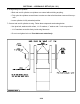
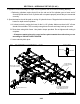
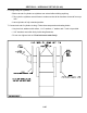
3. Charge depth control cylinder system.
– Connect depth control cylinder hoses to tractor. Insure that tips and couplers are CLEAN.
– Raise Coulter-Chisel. One cylinder will extend at a time. Do not allow anyone to stand near
Coulter-Chisel when it is raised or lowered.
– When all cylinders are fully extended, fully cycle the circuit four times to make sure all air has
been removed from system.
– Lower Coulter-Chisel plow before next step.
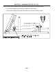
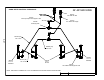
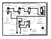
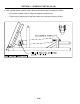
4. Hydraulic hoses and ttings for wing lift cylinders are shown in the following drawing.
– The wing lift hydraulic circuit is equipped with a one-way restrictor to prevent free fall of the
wings when being lowered. Be sure that the restrictor is installed so the arrow points toward
the cylinder. This will restrict oil owing out of the cylinder but not owing in.
– For 36’ & 40’ machines, 5 x 36” cylinders are used.
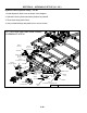
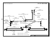
5. Route hoses along frame and hitch the same way depth control cylinder hoses are routed.
– Stack hoses on top of depth control hoses by using two hose clamps at each bolt.
– Leave enough slack by hitch pivot to allow full range of travel of the hitch without damage to
hoses.