COULTER-CHISEL DISK-CHISEL Operator’s Manual COULTER-CHISEL DISK-CHISEL COULTER-CHISEL DISK-CHISEL 2009 and newer IMPORTANT THE OPERATOR IS RESPONSIBLE FOR ADJUSTING THE MACHINE SINCE MACHINE DOES NOT COME “FIELD READY” FROM FACTORY. CAUTION READ & UNDERSTAND OPERATOR’S MANUAL BEFORE USING MACHINE. See www.summersmfg.com for the latest version of all Summers Operator’s Manuals. SUMMERS MANUFACTURING CO., INC. WEB SITE: www.summersmfg.com MADDOCK, NORTH DAKOTA 58348..................................
Warranty Summers warrants only products of its manufacture against operational failure caused by defective materials or workmanship which occur during normal use within 12 months from the date of purchase by the end user from Summers’ dealer.
INTRODUCTION This manual provides the following information about your Summers Coulter-Chisel and Disk-Chisel. SECTION CONTENTS Section 1 – SAFETY explains important safety precautions and familiarizes the Operator with the decals and their locations. Section 2 – ASSEMBLY includes step by step assembly instructions. Section 3 – COULTER-CHISEL & DISK-CHISEL OPERATION provides necessary information for the operation and adjustment of the machine.
TABLE OF CONTENTS SECTION 1 – SAFETY Safety-Alert Symbol.............................................................................................................................................. 1-1 General Safety Practices...................................................................................................................................... 1-1 Safety During Transport...........................................................................................................................
16’ & 20’ Depth Control Hydraulics....................................................................................................................... 6-5 16’-28’ Hydraulic Hitch.......................................................................................................................................... 6-6 24’-28’ Centers.....................................................................................................................................................
NOTES iv
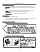
SECTION 1 - SAFETY SAFETY-ALERT SYMBOL This symbol is used to denote possible danger and care should be taken to prevent bodily injury. This symbol means: ATTENTION! BECOME ALERT! YOUR SAFETY IS INVOLVED! Definition of each Signal Word used in conjunction with the Safety-Alert symbol. DANGER indicates an imminently hazardous situation which, if not avoided, will result in death or serious injury. This signal word is to limited to the most extreme situations.
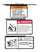
SAFETY DURING TRANSPORT SECTION 1 - SAFETY 1. ONLY TOW at a safe speed. Use caution when making corners or meeting traffic. 2. USE a safety chain between tractor drawbar and implement hitch when transporting on public roads. 3. ALWAYS use hydraulic cylinder transport locks when transporting on public roads. 4. FOLLOW ALL local laws governing transporting of farm machinery. 5. Frequently check for traffic from rear, especially during turns. SAFETY DECALS 1. KEEP SAFETY DECALS CLEAN. 2.
SECTION 1 - SAFETY 3. PN 8Z0202 – DECAL FOR COMPANY IDENTIFICATION 4. PN 8Z0276 – DECAL FOR GENERAL CAUTION 5.
SECTION 1 - SAFETY 6. PN 8Z0342 – DECAL FOR INSTALLING CYLINDER LOCKS 7. PN 8Z0344 – DECAL FOR STAYING CLEAR OF WINGS 8.
SECTION 1 - SAFETY 9. PN 8Z0348 – DECAL FOR GAUGE WHEEL DEPTH 10. PN 8Z0800 – AMBER REFLECTOR 11. PN 8Z0805 – RED-ORANGE REFLECTOR 12. PN 8Z0810 – RED REFLECTOR SAFETY LIGHT OPERATION The Summers Safety Light Kit is equipped with a 7 pin connector which meets SAE J560 specification. To protect 7 pin connector, store in dust cap (8K8067) when not attached to towing vehicle. On most towing vehicles WITHOUT brake lights: Amber lights will turn on with flashers or turn signals.
SECTION 1 - SAFETY 8Z0810 8Z0805 8Z0342 8Z0805 8Z0344 8Z0810 8Z0342 8Z0805 8Z0344 8Z0810 8Z0087 8Z0344 8Z0202 8Z0346 8Z0136 8Z0348 8Z0276 5/31/2013 1-6 9CC3212.
SECTION 2 – ASSEMBLY INTRODUCTION GENERAL ASSEMBLY SAFETY PRACTICES 1. READ AND UNDERSTAND Operator’s Manual before assembly of machine. 2. Machine should be assembled in a horizontal (field) position only. 3. If machine is to be assembled INDOORS, check that exit door is a MINIMUM OF 22’ WIDE. Height requirement varies up to 16’3”. Shanks may be left off to reduce height and width requirement. 4. Reference to “RIGHT” and “LEFT” is determined when machine IS VIEWED FROM THE REAR. 5.
SECTION 2 – ASSEMBLY INTRODUCTION GENERAL SAFETY PRACTICES YOU ARE RESPONSIBLE for the safe assembly of the machine. BLOCK UP ANY RAISED PART of the machine. Be sure machine is stable after blocking. DO NOT ALLOW CHILDREN or other unauthorized persons within the assembly area. ALWAYS INSPECT LIFTING CHAINS AND SLINGS for damage or wear. BE SURE LIFTING DEVICE IS RATED TO HANDLE THE WEIGHT.
SECTION 2 – SET-UP OF 16’ & 20’ DISK-CHISEL & COULTER-CHISEL MAIN FRAME 1. Place front, center and rear sections on floor with bolt plates facing each other. 2. ATTACH sections with 48 – 3/4x2-1/4” bolts, lock washers and nuts as shown. 8CC5018 16' & 20' CENTER 2-3 9CC2012H.iam/CENTER 7/18/2012 8CC5016 8K5515 3/4 X 4 X 6" 8X0260 3/4" N 8X0306 3/4" LW 8CC5230 8X0112 3/4X2-1/4" 8X0306 3/4" LW 8X0260 3/4" N 8T4030 - 16' REAR 8CC4028 - 20' REAR (SHOWN) 3. Block center frames off the floor.
SECTION 2 – SET-UP OF 16’ & 20’ DISK-CHISEL & COULTER-CHISEL MAIN FRAME 4. Install cylinder attach brackets with 3/4” u-bolts. NOTE: – Locate Rear Cylinder Attach Brackets (8T4224) 62” from frame center. 5. Insert eyebolts (8K1683) into each cylinder attach bracket. – Tighten 1-1/2” nuts so the same amount of threads are above top nut on all eyebolts. Insure that cylinder attach holes are aligned when eyebolts are tightened. 6. Liftarms will be centered beneath cylinder attach brackets.
8X0285 1 1/2" N 8P7250 8X0260 3/4" N 8CC0800 8CC0805 8X0306 3/4" LW 8K5515 3/4 X 4 X 6" 8X0203 3/8" FN 8X0285 1 1/2" N 8X0246 1/2" FN 8T4224 8T2040 D ETAIL A 62 " 62 A " 2-5 8CC4010 8K1683 8X0120 3/4" X 9" 8CC4000 8X0044 7/16" X 3-1/2" 8K1640 8X0234 7/16" LNUT 8X0306 3/4" LW 8CC4012 8X0260 3/4" N 7/18/2012 9CC2012H/CENTER W-CYL.
8X0110 3/4 X 1.25" 8X0000 1/4 X 3/4" 8K8067 8T4190 LEFT 8T4192 RIGHT 8X0072 1/2" X 3-3/4" 8X0318 3/4" FW 8D8490 8X0203 3/8" FN 8X0234 7/16" LNUT 8T3620 8X0223 1/4" FN 8X0234 7/16" LNUT DETAIL A DETAIL B 8X0044 7/16" X 3-1/2" 8K1100 8X0260 3/4" N 2-6 8K5515 3/4 X 4 X 6" 8X0306 3/4" LW A 8CC4140 B 8T4166 LEFT 8T4168 RIGHT 8X0044 7/16" X 3-1/2" 8K1660 8X0234 7/16" LNUT 8CC1310 8T4100 8X0368 1-1/2" FW 8T3640 8X0234 7/16" LNUT 7/18/2012 8X0044 7/16" X 3-1/2" 8K7033 9CC2012H.
8K8435 8D9108 1/4 X 2" RP 8X0306 3/4" LW 8X0260 3/4" N 8K5515 3/4 X 4 X 6" 2-7 8X0044 7/16" X 3-1/2" 8X0368 1-1/2" FW (AS REQUIRED) 8K1660 8X0234 7/16" LNUT 8CC1310 - 20' (SHOWN) 8CC1300 - 16' 7/18/2012 9CC2012H.
SECTION 2 – SET-UP OF 24’-28’ DISK-CHISEL & COULTER-CHISEL MAIN FRAME 1. Place front, center and rear sections on floor with bolt plates facing each other. 2. ATTACH sections with 48 – 3/4x2-1/4” bolts, lock washers and nuts as shown. 2-8 9CC2412H.iam/CENTERS 7/13/2012 8X0306 3/4" LW 8CC5060 8X0260 3/4" N 8CC5230 8CC5062 8X0306 3/4" LW 8K5515 3/4 X 4 X 6" 8X0112 3/4X2-1/4" 8X0260 3/4" N 8CC5070 3. Block center frames off the floor.
SECTION 2 – SET-UP OF 24’-28’ DISK-CHISEL & COULTER-CHISEL MAIN FRAME 4. Install cylinder attach brackets with 3/4” u-bolts. NOTE: – Locate Rear Cylinder Attach Brackets (8T4224) 66” from frame center. 5. Insert eyebolts (8K1683) into each cylinder attach bracket. – Tighten 1-1/2” nuts so the same amount of threads are above top nut on all eyebolts. Insure that cylinder attach holes are aligned when eyebolts are tightened. 6. Liftarms will be centered beneath cylinder attach brackets.
66 ” q 66 ” 8X0285 1 1/2" N 8X0285 1 1/2" N 2-10 8X0260 3/4" N 8X0306 3/4" LW 8K1683 8K5515 3/4 X 4-1/16 X 6" 8/6/2014 9CC2412H.iam/CENTER W-CYL.
8T1050 8X0260 3/4" N 8X0306 3/4" LW 8D9524 8T1055 8CC4140 8K5515 3/4 X 4 X 6" 8D9108 1/4 X 2" RP 2-11 8A1156 3/8 X 4-1/16 X 5" 8K9106 8CC4140 8X0203 3/8" FN 8T4190 8T4166 8K1100 A 8X0282 8X0044 7/16" X 3-1/2" 8X0260 3/4" N 8X0316 1" FW 8X0072 1/2" X 3-3/4" B 8T3620 8L0252 DETAIL A 8T3300 8L0252 8T3800 8X0306 3/4" LW 8T3640 8X0234 7/16" LNUT DETAIL B 8X0242 NY-LOCK 1/2" N 8T4100 8K5515 3/4 X 4 X 6" 8X0234 7/16" LNUT 8K7033 8X0044 7/16" X 3-1/2" 7/13/2012 9CC2412H.
8A1156 3/8 X 4-1/16 X 5" 8P7250 8T2040 8X0021A 5/16 X 1" 8X0211 5/16" FN 8K8200 8S1124 8S1126 8X0203 3/8" FN DETAIL B B DETAIL A 8T4350 8X0402 8S1120 8X0440 8X0240 1/2" N 8X0303 1/2" LW 2-12 8S0340 1/2 X 4 X 5 1/4" SQ 8T4380 A 8CC4010 8CC4000 8X0044 7/16" X 3-1/2" 8X0306 3/4" LW C 8CC0600 8D8522 8X0120 3/4" X 9" 8X0260 3/4" N 8X0318 3/4" FW 8K1640 8X0110 3/4 X 1.25" 8D8500 8K8067 8X0234 7/16" LNUT 8X0000 1/4 X 3/4" 8X0223 1/4" FN 8CC4012 8D8490 7/13/2012 DETAIL C 9CC2412H.
SECTION 2 – SET-UP OF 24’-28’ DISK-CHISEL & COULTER-CHISEL MAIN FRAME 16. Install (8T2040) Cylinder and secure with pins as shown. 17. Attach hydraulic hose holder and tip holder with 3/4 x 1-1/4” bolt and flat washer. 18. Attach hitch jack to jack spool. 19. Remove blocks from under center frame and allow wheel assemblies to support machine. Block tires to prevent movement. 20. Add depth control cylinder locks and storage bases. 21. Install SMV sign mounting bracket and sign at center of rear rank. 22.
SECTION 2 – SET-UP OF 24’-28’ DISK-CHISEL & COULTER-CHISEL WINGS NOTE: It is recommended to set up both sides of machine at the same time. The left hand side is shown. 1. Attach wing to center section with pins, washers, bolts and locknuts. – Washers are used to center wing in hinges and prevent shift. 2. Fasten cylinder attach brackets with 3/4” u-bolts, located 126-1/2” from machine center. 3. Insert eyebolts (8K1683) into cylinder attach bracket.
8T1060 8T4175 8L0300 8T4177 8D9108 1/4 X 2" RP 8S0660 8X0240 1/2" N 8X0303 1/2" LW 8T4168 8K9106 8T3620 DETAIL B 2-15 B 8X0234 7/16" LNUT 8X0044 7/16" X 3-1/2" 8CC4140 8T4174 8X0044 7/16" X 3-1/2" 8X0077 1/2" X 7-1/2" 8T3640 8S0660 8X0242 NY-LOCK 1/2" N DETAIL A 8K7033 8X0260 3/4" N 8X0234 7/16" LNUT 8T4179 8K1100 A 8K5515 3/4 X 4 X 6" 8X0306 8T4100 3/4" LW 8R6914 8X0074 1/2" X 4-1/2" 8/31/2012 9DC2412H.
SECTION 2 – SET-UP OF 24’-28’ DISK-CHISEL & COULTER-CHISEL WINGS – Insert 7/16 x 3-1/2” bolt in retaining bolt hole. Secure with lock nut. 5. Install walking tandem assembly to bottom of liftarm. – The left hand wing uses a right hand assembly – 8T4168. – The right hand wing uses a left hand assembly – 8T4166. – Slide pivot pin (8T3620) through walking tandem assembly and liftarm. – Insert 7/16 x 3-1/2” bolt in retaining bolt hole. Secure with lock nut. 6. Hang cylinders in appropriate location.
8X0306 3/4" LW 8X0260 3/4" N 2-17 8T4060 26'-28' ONLY 8CC4075 28' ONLY 7/13/2012 9DC2812H.
8X0260 3/4" N 8K8435 2-18 8X0306 3/4" LW 8CC1320 8D9108 1/4 X 2" RP 8K9102 8CC1005 8K1660 8X0044 7/16" X 3-1/2" 8K5515 3/4 X 4 X 6" 8X0368 1-1/2" FW 8CC1330 - 24' LEFT (SHOWN) 8CC1340 - 24' RIGHT 8CC1350 - 26-28' LEFT 8CC1360 - 26-28' RIGHT 8X0234 7/16" LNUT 7/13/2012 9CC2412H.
SECTION 2 – SET-UP OF DISK-CHISEL & COULTER-CHISEL CENTER SECTION (32’-40’) 1. Place front, center and rear sections on floor with bolt plates facing each other. 2. ATTACH sections with 48 – 3/4x2-1/4” bolts, lock washers and nuts as shown. 8CC5200 8X0112 3/4X2-1/4" 8X0306 3/4" LW 8/13/2012 8X0260 3/4" N 8CC5210 9CC3212.iam/CENTERS 8T4030 3. Block center frames off the floor.
SECTION 2 – SET-UP OF DISK-CHISEL & COULTER-CHISEL CENTER SECTION (32’-40’) 4. Install cylinder attach brackets with 3/4” u-bolts. NOTE: – Locate Rear Cylinder Attach Brackets (8T4224) 62” from frame center. 5. Insert eyebolts (8K1683) into each cylinder attach bracket. – Tighten 1-1/2” nuts so the same amount of threads are above top nut on all eyebolts. Insure that cylinder attach holes are aligned when eyebolts are tightened. 6. All liftarms will be centered beneath cylinder attach brackets.
8X0306 3/4" LW 8X0285 1 1/2" N 8T4224 8X0318 3/4" FW 8CC6028 8X0111 3/4" X 2-1/2" 8X0318 3/4" FW 8X0306 3/4" LW 8X0285 1 1/2" N DETAIL A 8X0260 3/4" N 8X0306 3/4" LW 8X0260 3/4" N 8CC6015 8X0130 7/8" X 2" 2-21 8X0307 7/8" LW 8K1683 8X0132 7/8" X 2-1/2" 8K5515 3/4 X 4 X 6" A 8X0307 7/8" LW 8X0268 7/8" N 8X0285 1 1/2" N 8X0315 1-1/2" LW 8CC6010 8X0155 1.5" X 9" 8/13/2012 9DC4012.
SECTION 2 – SET-UP OF DISK-CHISEL & COULTER-CHISEL CENTER SECTION (32’-40’) 11. Insert 1-1/2 x 10-3/8” eyebolts into wing lift cylinder attach base. – Leave 1-1/2” nuts loose, they will need to be adjusted after wing is installed. 12. Attach wing lift cylinders to frame with pins and roll pins. – 32’ machine uses 4 x 36” cylinders (8K9640). – 36’ & 40’ machines use 5 x 36” cylinders (8K9650).
SECTION 2 – SET-UP OF DISK-CHISEL & COULTER-CHISEL WINGS (32’-40’) NOTE: It is recommended to set up both sides of machine at the same time. The left hand side is shown. 1. Attach wing to center section with pins, washers, bolts and locknuts. – Washers are used to center wing in hinges and prevent shift. 2. Fasten cylinder attach brackets with 3/4” u-bolts, located 169” from machine center. 3. Insert eyebolts (8K1755) into cylinder attach bracket.
SECTION 2 – SET-UP OF DISK-CHISEL & COULTER-CHISEL WINGS (32’-40’) 5. Install walking tandem assembly to bottom of liftarm. – The left hand wing uses a right hand assembly – 8T4168. – The right hand wing uses a left hand assembly – 8T4166. – Slide pivot pin (8T3620) through walking tandem assembly and liftarm. – Insert 7/16 x 3-1/2” bolt in retaining bolt hole. Secure with lock nut. 6. Hang cylinders in appropriate location. Use pins and roll pins. – Rod end of cylinder must point towards ground.
SECTION 2 – SET-UP OF DISK-CHISEL & COULTER-CHISEL CENTER SECTION (32’-40’) SECTION 2 – SET-UP OF DISK-CHISEL & COULTER-CHISEL CENTER SECTION (32’-40’) 8T4190 LEFT 8T4192 RIGHT 8X0203 3/8" FN 8A1156 3/8 X 4-1/16 X 5" 8X0242 NY-LOCK 1/2" N 8X0072 1/2" X 3-3/4" DETAIL C 8K1100 8T4166 LEFT 8T4168 RIGHT C 8K7033 8T4096 8X0307 7/8" LW 8X0268 7/8" N 8X0242 NY-LOCK 1/2" N 8K1100 8T3120 8X0261 3/4" LN 8X0322 1/2" FW 8X0234 7/16" LNUT 8K5515 8D0340 3/4 X 4 X 6" 3/4 X 4 X 7-3/4" 8X0260 8X0306 8L1110 3/4"
SECTION 2 – SET-UP OF DISK-CHISEL & COULTER-CHISEL CENTER SECTION (32’-40’) SECTION 2 – SET-UP OF DISK-CHISEL & COULTER-CHISEL CENTER SECTION (32’-40’) 8T1045 8T4190 LEFT 8T4192 RIGHT 8X0203 3/8" FN 8A1156 3/8 X 4-1/16 X 5" 8X0242 NY-LOCK 1/2" N 8T1050 8X0072 1/2" X 3-3/4" DETAIL C 8T1055 C 8K1105S 8T4166 LEFT 8T4168 RIGHT 8K7037 8T1060 8T3120 8X0261 3/4" LN 8X0242 NY-LOCK 1/2" N 8D3031 8X0268 7/8" N 8R6914 8T4096 8X0307 7/8" LW 8K1100 8X0242 NY-LOCK 1/2" N DETAIL A 8T3640 8X0067 1/2-13NCX
SECTION 2 – SET-UP OF DISK-CHISEL & COULTER-CHISEL CENTER SECTION (32’-40’) 15. Attach gauge wheel jack handle to screw top. – Install 3/8 x 2” bolt in handle and screw top. Secure with lock nut. – Do not over tighten. Handle must pivot freely. 16. Check free operation of gauge wheel assembly. – Loosen or tighten slotted nut for optimum performance of gauge wheel. – Install 3/16” x 2” roll pin after slotted nut is adjusted properly. 16a.
SECTION 2 – SET-UP OF DISK-CHISEL & COULTER-CHISEL CENTER SECTION (32’-40’) – Install rectangular washer (8CC6035) with 1-1/4” lockwasher and nut onto bottom of caster arm. – Install hubs (8K1105S) as shown and retain with 1/2 x 3-3/4” bolt and nylock nut. – Attach wheel and tire assemblies. Tighten lug nuts to 240 ft-lbs. 28. Tighten slotted nut (8X0292) so that caster wheel assembly cannot be moved by human force. – Retain slotted nut with 3/8” hardware as shown. 29.
8D9108 1/4 X 2" RP 8K9106 8T1037 8L0246 8CC6026 8CC6022 8X0133 7/8 X 3" 2-29 8X0307 7/8" LW 8CC6000 8X0268 7/8" N 8X0044 7/16" X 3-1/2" 8T3620 8/15/2012 8X0234 7/16" LNUT 9DC4012.
SECTION 2 – SET-UP OF 32’-40’ CASTER WHEELS & HITCH 8X0202 3/8" LN 8X0320 3/8" FW 2-30 8X0015 3/8" X 3 3/4" 8K5200 8X0292 2" SLTD N 7L2150 8L0320 8L0320 7P8530 8X0261 3/4" LN 8K7042 8X0072 1/2" X 3-3/4" 8X0113 3/4 X 5" 8K1105S 8CC6035 8X0311 1 1/4" LW 8X0284 1 1/4" N 8CC6030 8X0242 NY-LOCK 1/2" N 6/24/2013 9DC4012.
8D8500 8X0000 1/4 X 3/4" 8X0318 3/4" FW 8X0223 1/4" FN 8K3002 8D8490 DETAIL A 2-31 A 8W1398 8X0044 7/16" X 3-1/2" 8X0203 3/8" FN 8K1640 8CC0600 8CC4000 32' - 36' 8T4000 40' ONLY WRENCH HOLDER STUDS 8X0234 7/16" LNUT 8C1710 3/8 X 8 X 9" 8T0608 8D8522 8T0606 NOTE: 8K3002 WRENCHES AND 8CC0600 WRENCH HOLDERS USED ON COULTER-CHISELS ONLY. 8T0606 AND 8T0608 WRENCHES USED ON DISK-CHISELS ONLY 8/17/2012 9CC3212.iam/HITCH SECTION 2 – SET-UP OF 32’-40’ CASTER WHEELS & HITCH 8X0110 3/4 X 1.
SECTION 2 – SET-UP OF 32’-40’ CASTER WHEELS & HITCH 33. Remove blocks from under center frame and allow wheel assemblies to support machine. Block tires to prevent movement. 34. Add depth control cylinder locks and storage bases. – Attach locks for rear cylinders by liftarm pivots located closest to center of machine. – Locate lock for front center cylinder on front 4 x 4 tube. 35. Install SMV sign mounting bracket and sign at center of rear rank.
16' & 20' MACHINES 8N4228 1/2" X 228" 8T1060 TOP VIEW TO TRACTOR 8T1060 8T1010 POPPET 8T1008 PLASTIC PLUNGER REPAIR KIT 2-33 8T1055 8J5520 3/4" ORB X #10 STR 8N4546 1/2" X 546" 8J5520 3/4" ORB X #10 STR 8D3212 3/4" ORB TIP ISO 8N6570 3/4" X 570" 8J5520 3/4" ORB X #10 STR 8D3212 3/4" ORB TIP ISO 9/12/2012 CC-DC DEPTH CNTRL HYD SECTION 2 – HYDRAULIC SET-UP (16’ & 20’) 8J6020 3/4"-16ORB X 10 JIC(M) 90° ADP TO 8T1055
16' & 20' COULTER-CHISEL GANG DEPTH CONTROL HYDRAULICS SECTION 2 – HYDRAULIC SET-UP (16’ & 20’) 8N3070 4X 8X0082 1/2" X 6-1/2" 8X0001 3/8 X 3/4" 8CC0805 8Z0365 2-34 8X0203 3/8" FN 8J5300 #6 JIC(M) TEE 8CC0800 8X0246 1/2" FN 8D3212 3/4" ORB TIP ISO 8X0202 3/8" LN 8J5510 3/4" OR B X #6 JIC(M) 8N3312 2X 8CC0600 8J6010 3/4-16ORB X #6JIC(M) 90° ADP 8C1710 3/8 X 8 X 9" 7/13/2012 9CC2012H.
SECTION 2 – HYDRAULIC SET-UP (24’ - 28’) 1. Hydraulic hoses and fittings for depth control cylinders can be found on following drawing. – Rephasing cylinders require that oil from the rod end of first cylinder goes to base end of second cylinder and so forth. Cylinders will not operate properly unless they are connected correctly. 2. Special attention should be paid to routing of hydraulic hoses. Diagram below shows layout of hoses for depth control cylinders. A.
SECTION 2 – HYDRAULIC SET-UP (24’ - 28’) 3. Charge depth control cylinder system. – Connect depth control cylinder hoses to tractor. Insure that tips and couplers are CLEAN. – Raise Coulter-Chisel. One cylinder will extend at a time. Do not allow anyone to stand near Coulter-Chisel when it is raised or lowered. – When all cylinders are fully extended, fully cycle the circuit four times to make sure all air has been removed from system. – Lower Coulter-Chisel plow before next step. 4.
24' - 28' MACHINES 8J6020 3/4"-16ORB X 10 JIC(M) 90° ADP 8N4198 1/2" X 198" 8N4198 1/2" X 198" 8J5520 3/4" ORB X #10 STR 8J6020 3/4"-16ORB X 10 JIC(M) 90° ADP 8T1060 8T1055 8T1050 8N4228 1/2" X 228" 8J6010 3/4-16ORB X #6JIC(M) 90° ADP 2-37 8N3534 3/8" X 534" 8N6570 3/4" X 570" TO 8T1055 8J5510 3/4" ORB X #6 JIC(M) 8J5520 3/4" ORB X #10 STR 8T1010 POPPET 8T1008 PLASTIC PLUNGER REPAIR KIT 8T1060 TOP VIEW TO TRACTOR 8D3212 3/4" ORB TIP ISO 9/12/2012 CC-DC DEPTH CNTRL HYD SECTION 2 – HYDRAULIC
24'-28' MACHINE WING LIFT HYDRAULICS 8D3212 3/4" ORB TIP ISO 8J5300 #6 JIC(M) TEE 2-38 8J7116 ARROW MUST POINT TOWARD CYLINDER 8J5510 3/4" ORB X #6 JIC(M) 8J5620 3/4" X #6 JIC (F-SW) 8J7040 THERMAL RELIEF 8J5200 #10(F)X#6(M) BUSH 8J6030 7/8"X#10(M) 90° ADP 8J5680 3/4"X3/4" UNION 8N3288 3/8" X 288" 8J5510 3/4" ORB X #6 JIC(M) 8N3048 3/8" X 48" 8J7116 8J6030 7/8"X#10(M) 90° ADP 8J5700 #6 JIC(F-SW) X #6 JIC(M) 90° ADP 8J6030 7/8"X#10(M) 90° ADP 8J5620 3/4" X #6 JIC (F-SW) 8N3028 8J5200 3/8" X 28" #
SECTION 2 – HYDRAULIC SET-UP (24’ - 28’) 6. Charge Wing Lift Cylinders. – Block rod end of cylinders so cylinders can extend without hitting anything. – Fully cycle the cylinders several times to make sure that all air has been removed from system. – Leave cylinders in fully extended position. 7. Connect rod end of cylinders to wing. Follow these steps and see drawing below. – Use pivot bolt, washers with collars, 1-1/4” washers, 1” washer and 1” lock nut provided.
SECTION 2 – HYDRAULIC SET-UP (24’ - 28’) 8. With cylinder attach eyebolts loose, raise coulter-chisel wings to transport position. – Fully retract cylinders and let wings rest against transport locks. – Tighten each eyebolt so pivot bolt and rollers are centered in the wing lift slot.
24'-28' MACHINE GANG DEPTH CONTROL HYDRAULICS 8D3212 3/4" ORB TIP ISO 8N3312 (2X) 3/8" X 312" 8J5700 #6 JIC(F-SW) X #6 JIC(M) 90° ADP 8J5510 3/4" ORB X #6 JIC(M) 8N3150 (2X) 3/8" X 150" 2-41 8N3096 (2X) 3/8" X 96" 8K8435 3.5 X 8" MASTER 8N3124 (2X) 3/8" X 124" 8K8430 3 X 8" SLAVE 8K8435 3.
SECTION 2 – HYDRAULIC SET-UP (16’ - 28’) Hydraulic Hitch Hydraulic Setup - 16’-28’ 1. Install Hydraulic hitch hose as shown in the diagram. 2. Hydraulic Hitch cylinder should be plumbed in parrallel. 3. Route hose along hitch frame. 4. Use provided clamps and plastic ties to secure hoses.
SECTION 2 – HYDRAULIC SET-UP (32’-40’) 1. Hydraulic hoses and fittings for depth control cylinders can be found on following drawing. – Rephasing cylinders require that oil from the rod end of first cylinder goes to base end of second cylinder and so forth. Cylinders will not operate properly unless they are connected correctly. 2. Special attention should be paid to routing of hydraulic hoses. Diagrahm below shows layout of hoses for depth control cylinders. A.
32'-40' DISK- / COULTER- CHISEL CASTER HYD.
SECTION 2 – HYDRAULIC SET-UP (32’-40’) 3. Charge depth control cylinder system. – Connect depth control cylinder hoses to tractor. Insure that tips and couplers are CLEAN. – Raise Coulter-Chisel. One cylinder will extend at a time. Do not allow anyone to stand near Coulter-Chisel when it is raised or lowered. – When all cylinders are fully extended, fully cycle the circuit four times to make sure all air has been removed from system. – Lower Coulter-Chisel plow before next step. 4.
32'-40' MACHINE WING LIFT HYDRAULICS 8D3212 3/4" ORB TIP ISO 8N3360 3/8" X 360" + 8J5100 UNION + 8N3060 3/8" X 60" 8J5700 #6 JIC(F-SW) X #6 JIC(M) 90° ADP 8J5690 3/4-16X3/4-16 ORB M-SW 90° UNION 8J5300 #6 JIC(M) TEE 2-46 8J5510 3/4" ORB X #6 JIC(M) 8J7116 ARROW MUST POINT TOWARD CYLINDER 8J5680 3/4"X3/4" UNION 8J7040 THERMAL RELIEF 8A1954 1/4"OD TUBE - 18" 8J6010 3/4-16ORB X #6JIC(M) 90° ADP 8N3070 3/8" X 70" 8J5700 #6 JIC(F-SW) X #6 JIC(M) 90° ADP 8N3035 3/8" X 35" 8J6010 3/4-16ORB X #6JIC(M) 90
SECTION 2 – HYDRAULIC SET-UP (32’-40’) 6. Charge Wing Lift Cylinders. – Block rod end of cylinders so cylinders can extend without hitting anything. – Fully cycle the cylinders several times to make sure that all air has been removed from system. – Leave cylinders in fully extended position. 7. Connect rod end of cylinders to wing. Follow these steps and see drawing below. – Use pivot bolt, washers with collars, 1-1/4” washers, 1” washer and 1” lock nut provided.
SECTION 2 – HYDRAULIC SET-UP (32’-40’) 8. With cylinder attach eyebolts loose, raise coulter-chisel wings to transport position. – Fully retract cylinders and let wings rest against transport locks. – Tighten each eyebolt so pivot bolt and rollers are centered in the wing lift slot.
32'-36' MACHINE GANG DEPTH CONTROL HYDRAULICS 8D3212 3/4" ORB TIP ISO 8N3312 (2X) 3/8" X 312" 8J5700 #6 JIC(F-SW) X #6 JIC(M) 90° ADP 8J5510 3/4" ORB X #6 JIC(M) 2-49 8N3180 (2X) 3/8" X 180" 8N3096 (2X) 3/8" X 96" 8K8435 3.5 X 8" MASTER 8N3136 (2X) 3/8" X 136" 8K8435 3.
GANG DEPTH CONTROL HYDRAULICS 8J5700 #6 JIC(F-SW) X #6 JIC(M) 90° ADP 40' MACHINE 8D3212 3/4" ORB TIP ISO 8N3312 (2X) 3/8" X 312" 8J5510 3/4" ORB X #6 JIC(M) 8J5300 #6 JIC(M) TEE SECTION 2 – HYDRAULIC SET-UP (40’) 8N3180 (2X) 3/8" X 180" 2-50 8N3084 (2X) 3/8" X 84" 8K8435 3.5 X 8" MASTER 8K8430 3 X 8" SLAVE 8N3160 (2X) 3/8" X 160" 8K8435 3.
8X0082 1/2" X 6-1/2" 8X0001 3/8 X 3/4" 8CC0810 SECTION 2 – HYDRAULIC SET-UP (ALL WIDTHS) 8X0203 3/8" FN 8X0016 3/8" X 3" 8X0203 3/8" FN 2-51 8CC0800 8X0246 1/2" FN 8CC0805 8CC0815 8Z0365 4/4/2013 9CC3212.
SECTION 2 – INSTALLATION OF SHANKS AND COULTER GANGS 8X0260 3/4" N 8X0118 3/4 X 4" 8X0306 3/4" LW 8T7500 700 LB TRIP (BLACK SPRING) OR 8T7500H 1050 LB TRIP (GREEN SPRING) 8X0306 3/4" LW 8X0260 3/4" N 8T0504 (GREEN) 8T0500 (BLACK) 8K5515 3/4 X 4 X 6" 8/17/2012 1. Install shanks into trip assemblies. – Install rear 3/4 x 4” bolt. Slide shank into shank holder. Install front bolt. Securely tighten. – Shanks will fit snuggly into shank holder.
SECTION 2 – INSTALLATION OF SHANKS AND COULTER GANGS 2-53
SECTION 2 – INSTALLATION OF SHANKS AND COULTER GANGS 1. Gang Mounting – Start from the center and work towards the outside when hanging the gangs. Bearing location is important, use correct gang assembly for each location. Carefully lift gang to frame close to correct location. Attach C-shanks to frame using (2) 3/4” U-bolts, mounting plate with peg, flat mounting plate, lockwashers and nuts. After both C- shanks on each gang are mounted, slide the gang to its proper location and tighten hardware. 2.
16' SHANK LAYOUT 65 1/2" 2-55 78" 6" 53" 42" 18" 90" 6" -- : SUGGESTED TWISTED SPIKE LAYOUT 8/29/2012 9CC1612H.
16' DISK-CHISEL A 97 3/4" 77 3/4" 57 3/4" 37 3/4" 17 3/4" 0" 2-56 WHEN LOCATING BLADE, USE CENTER HOLE ON REAR OF BRACKET, AS SHOWN. DIMENSION SHOWN IS FROM CENTERLINE OF MACHINE TO THIS HOLE. DETAIL A 16' COULTER-CHISEL 8CC2280F 8CC2280F 48" 8J3276 23 1/2" 8J3286 71 3/4" 8/29/2012 9DC1612H.
20' SHANK LAYOUT 2-57 90" 18" 102" 53" 114" 78" 42" 6" 6" -- : SUGGESTED TWISTED SPIKE LAYOUT 8/29/2012 9CC2012H.
20' DISK-CHISEL A 117 3/4" 97 3/4" 77 3/4" 57 3/4" 37 3/4" 17 3/4" 0" 2-58 WHEN LOCATING BLADE, USE CENTER HOLE ON REAR OF BRACKET, AS SHOWN. DIMENSION SHOWN IS FROM CENTERLINE OF MACHINE TO THIS HOLE. DETAIL A 20' COULTER-CHISEL 8CC2260F 8CC2260F 48" 8J3266 8CC2280F 24 1/4" 73 3/4" 93 3/4" 8J3266 8J3276 8/29/2012 9CC2012H.
24' SHANK LAYOUT 126" 66" 30" 2-59 90" 18" 138" 54" 6" 6" 114" 78" 42" -- : SUGGESTED TWISTED SPIKE LAYOUT 8/30/2012 9CC2412H.
24' DISK-CHISEL 48" A 136 3/4" 96 3/4" 116 3/4" 56 3/4" 76 3/4" 16 3/4" 36 3/4" 0" 0" 2-60 WHEN LOCATING BLADE, USE CENTER HOLE ON REAR OF BRACKET, AS SHOWN. DIMENSION SHOWN IS FROM CENTERLINE OF MACHINE TO THIS HOLE. DETAIL A 24' COULTER-CHISEL 8CC2250F 8J3246 114 3/4" 8CC2260F 8J3266 8CC2281F 8CC2252F 48" 38 1/4" 58 1/4" 60 5/8" 8J3276 8J3246 108 1/4" 132 1/2" 8/30/2012 9DC2412H.
26' SHANK LAYOUT 126" 66" 30" 2-61 90" 18" 138" 54" 6" 6" 150" 114" 78" 42" -- : SUGGESTED TWISTED SPIKE LAYOUT 8/30/2012 9CC2612H.
26' DISK-CHISEL 48" A 136 3/4" 156 3/4" 96 3/4" 116 3/4" 56 3/4" 76 3/4" 16 3/4" 36 3/4" 0" 0" 2-62 WHEN LOCATING BLADE, USE CENTER HOLE ON REAR OF BRACKET, AS SHOWN. DIMENSION SHOWN IS FROM CENTERLINE OF MACHINE TO THIS HOLE. DETAIL A 26' COULTER-CHISEL 8CC2260F 8J3256 114 3/4" 8CC2260F 8J3266 8CC2281F 8CC2260F 48" 38 1/4" 58 1/4" 60 5/8" 8J3276 8J3256 110 1/4" 130 1/4" 8/30/2012 9DC2612H.
28' SHANK LAYOUT 162" 126" 66" 30" 2-63 90" 18" 138" 54" 6" 6" 150" 114" 78" 42" -- : SUGGESTED TWISTED SPIKE LAYOUT 8/30/2012 9CC2812H.
28' DISK-CHISEL 48" A 136 3/4" 156 3/4" 96 3/4" 116 3/4" 56 3/4" 76 3/4" 16 3/4" 36 3/4" 0" 0" 2-64 WHEN LOCATING BLADE, USE CENTER HOLE ON REAR OF BRACKET, AS SHOWN. DIMENSION SHOWN IS FROM CENTERLINE OF MACHINE TO THIS HOLE. DETAIL A 28' COULTER-CHISEL 8CC2261F 8J3256 8CC2261F 114 3/4" 8CC2282F 8CC2281F 48" 8J3256 8J3276 12" 8J3286 72 1/2" 156 1/2" 108" 8/30/2012 9DC2812H.
SECTION 2 – INSTALLATION OF SHANKS AND COULTER GANGS SECTION 2 – INSTALLATION OF SHANKS AND COULTER GANGS 32' SHANK LAYOUT 174" 126" 65 1/2" 150" 18" 138" 90" 186" 30" 102" 53" 162" 114" 78" 42" 6" 6" -- : SUGGESTED TWISTED SPIKE LAYOUT 8/30/2012 2-65 9CC3212.
SECTION 2 – INSTALLATION OF SHANKS AND COULTER GANGS 32' DISK-CHISEL SECTION 2 – INSTALLATION OF SHANKS AND COULTER GANGS 153" A 177 1/4" 197 1/4" 137 1/4" 157 1/4" 97 1/4" 117 1/4" 48" 57 1/4" 77 1/4" 16 1/4" 37 1/4" 0" 0" WHEN LOCATING BLADE, USE CENTER HOLE ON REAR OF BRACKET, AS SHOWN. DIMENSION SHOWN IS FROM CENTERLINE OF MACHINE TO THIS HOLE.
SECTION 2 – INSTALLATION OF SHANKS AND COULTER GANGS SECTION 2 – INSTALLATION OF SHANKS AND COULTER GANGS 36' SHANK LAYOUT 174" 126" 65 1/2" 30" 210" 150" 138" 18" 186" 90" 102" 53" 162" 198" 6" 114" 42" 6" 78" -- : SUGGESTED TWISTED SPIKE LAYOUT 8/30/2012 2-67 9CC3612.
SECTION 2 – INSTALLATION OF SHANKS AND COULTER GANGS 36' DISK-CHISEL SECTION 2 – INSTALLATION OF SHANKS AND COULTER GANGS 164" A 217 1/4" 177 1/4" 197 1/4" 137 1/4" 157 1/4" 48" 97 1/4" 57 1/4" 117 1/4" 77 1/4" 16 1/4" 37 1/4" 0" 0" WHEN LOCATING BLADE, USE CENTER HOLE ON REAR OF BRACKET, AS SHOWN. DIMENSION SHOWN IS FROM CENTERLINE OF MACHINE TO THIS HOLE.
SECTION 2 – INSTALLATION OF SHANKS AND COULTER GANGS SECTION 2 – INSTALLATION OF SHANKS AND COULTER GANGS 40' SHANK LAYOUT 164 1/16" 222" 174" 48" 126" 65 1/2" 198" 150" 186" 138" 18" 234" 90" 30" 102" 53" 78" 42" 6" 6" 114" 162" 210" -- : SUGGESTED TWISTED SPIKE LAYOUT 8/30/2012 2-69 9CC4012.
SECTION 2 – INSTALLATION OF SHANKS AND COULTER GANGS 40' DISK-CHISEL SECTION 2 – INSTALLATION OF SHANKS AND COULTER GANGS 164" A 217 1/4" 237 1/4" 177 1/4" 197 1/4" 137 1/4" 157 1/4" 48" 97 1/4" 117 1/4" 57 1/4" 77 1/4" 16 1/4" 37 1/4" 0" 0" WHEN LOCATING BLADE, USE CENTER HOLE ON REAR OF BRACKET, AS SHOWN. DIMENSION SHOWN IS FROM CENTERLINE OF MACHINE TO THIS HOLE.
SECTION 2 – GANG ASSEMBLY DISK-CHISEL BLADE ASSEMBLY NOTE POSITION OF BOLTS 16° 12° 24° 20° 8X0119 3/4 X 7-1/2" 8X0306 3/4" LW 8D5214 8CC1500 8X0260 3/4" N (4 CORNER BOLTS) 8CC1505 (LEFT) 8CC1507 (RIGHT) 8X0118 3/4 X 4" 8X0306 3/4" LW 8R6913 8X0265 3/4" LN (CNTR ONLY) 8X0415 8D5217 8D5217 8K4925 8K4922 8X0118 3/4 X 4" 8K4400 8D5238 8D5212 8D5219 7/8" FW 8D5209 8D5236 8D5234 8K4939 8K4944 NOTE: ASSEMBLY ABOVE IS FOR LEFT SIDE OF DISK-CHISEL.
SECTION 2 – WARNING DECALS (ALL SIZES) 1. Install danger, warning, and caution decals. – Part numbers can be found on lower right hand corner of each decal. Match this number with number on decal location drawing on Page 1-6. – The drawing gives approximate locations of decals. Decals must be clearly visible. – Order replacement decals if any are damaged. 2. Install reflectors. – Amber reflectors are part # 8Z0800, these should be placed on front corners and sides of machine in transport position.
SECTION 3 – OPERATION OPERATION SAFETY 1. READ AND UNDERSTAND Operator’s Manual before using machine. Review at least annually thereafter. 2. VERIFY that all safety devices and shields are in place before using machine. 3. KEEP hands, feet, hair and clothing away from moving parts. 4. STOP engine, place all controls in neutral, set parking brake, remove ignition key and wait for all moving parts to stop before servicing, adjusting, maintaining or unplugging. 5.
SECTION 3 – OPERATION INITIAL HOOKUP 1. Make tractor to hitch connection with locking draw pin and safety chain. 2. Retract jack and rotate into storage position. Connect Safety Light Kit to 7 pin receptacle. 3. Plug wing lift hoses into desired tractor outlet. Insure that tips and couplers are CLEAN. 4. Plug depth control hoses into desired tractor outlet. 5. Park tractor and coulter-chisel on a level surface. 6. Remove transport lock pins on wings.
SECTION 3 – OPERATION 6. (Continued) WING LIFT CYLINDERS AT REST IN TRANSPORT POSITION. 7. Lower wings with caution. Do not raise or lower the wings when moving. Operate tractor hydraulics from operator station only. Do not allow any one near Coulter-Chisel when wings are raised or lowered. IMPORTANT A one-way restrictor is installed in wing lowering hydraulic circuit. This has been done to reduce chance of wing free fall. Do not remove this restrictor.
SECTION 3 – OPERATION 8. Fully extend depth control cylinders and maintain hydraulic pressure for 60 seconds to insure that all air has been purged from the system. NOTE: This machine has rephasing style depth control cylinders. When cylinders are fully extended, oil will bypass through a rephasing slot on each cylinder in order to equalize the system. 9. Remove depth control cylinder transport locks.
SECTION 3 – OPERATION 9. (Continued) – Store transport locks on holders. 10. Become familiar with single point depth control. Control can be found on 6 x 10 cylinder located on lefthand wing. A hairpin clip is used to hold plunger in desired location.
SECTION 3 – OPERATION FIELD OPERATION 1. Rephase cylinders before starting field operation. 2. Choose a flat spot in a field to set tillage depth and level machine. IMPORTANT! The operator is responsible for adjusting machine since machine does not come “Field Ready” from factory. 3. Determine desired tillage depth by working test strips within the field. NOTE: Optimum performance of machine is achieved by tilling at a depth and moving at a speed that does not go beyond limit of trip assemblies.
SECTION 3 – OPERATION 3. (Continued) – Trip Assembly Limit NOTE: Increased draft will occur if connecting bolt continually rides above trip assembly cap. This will consume horsepower as well as reduce life of trip assembly components. 4. After determining desired tillage depth, set depth control plunger accordingly. Standard plunger hole spacing gives 5/16” cylinder stroke adjustment. By rotating plunger 90 degrees, a half step adjustment is achieved.
SECTION 3 – OPERATION 5. Leveling coulter-chisel from side to side. Stop tractor with machine in the ground. Check depth of tillage on the left wing, center, and right wing. If leveling is necessary, use wrenches provided to adjust eyebolts on cylinder attachments located at rear of machine. *NOTE: Insure that cylinder attach holes are aligned when eyebolts are tightened. IMPORTANT! Pressure must be removed from cylinders before adjusting eyebolts.
SECTION 3 – OPERATION NOTE: It is best to check levelness after each adjustment by working test strips within the field. 6. Leveling machine from front to back. 16’ through 28’: Adjust hitch height to level machine at working depth. 32’-40’: With machine still in the ground, check depth of tillage in the front and the back. If leveling is necessary, use wrenches provided to adjust eyebolts on front wheel assemblies up or down.
SECTION 3 – OPERATION 7. Setting gauge wheels. After depth has been established and coulter-chisel has been leveled, operator must set gauge wheels. Stop tractor with coulter-chisel in the ground. Adjust crank assembly until wheel rests on top of the ground. Set bolts are installed on each gauge wheel assembly. Adjust set bolts so gauge wheel depth can still be changed but rotation of assembly is limited. If running at a consistent depth, set bolts can be securely tightened to lock gauge wheels.
SECTION 3 – OPERATION 8. Operation “Tips” – Floating hitch machines are designed to follow ground contours. This machine has a short wheel base in field position that allows it to smoothly follow through ditches and gullies. This machine will also follow deep furrows in the field. The operator may want to till through deep furrows at an angle to maintain a more uniform tillage depth. – Remember to rephase cylinders every hour.
SECTION 3 – OPERATION 4. Use a safety chain between tractor drawbar and coulter-chisel hitch when transporting. 5. Only tow at a safe speed – 20 MPH MAXIMUM. Use caution when making corners or meeting traffic. 6. Follow all local laws governing transporting of farm machinery. 7. Be aware of and comply with all height and width transport requirements. (See specifications page 5-2). 8. Stay clear of overhead lines. 9. Frequently check for traffic from rear, especially during turns. UNHOOKING FROM TRACTOR 1.
SECTION 4 – MAINTENANCE MAINTENANCE SAFETY 1. STOP engine, place all controls in neutral, set parking brake, remove ignition key and wait for all moving parts to stop before servicing, adjusting or maintaining. 2. BE CAREFUL when working around high pressure hydraulic system. 3. ALWAYS make sure that pressure is relieved from hydraulic circuits before servicing or disconnecting from tractor. 4. USE EXTREME CARE when making adjustments. 5. KEEP CHILDREN AWAY from machinery at all times. 6.
SECTION 4 – MAINTENANCE DAILY MAINTENANCE 1. Grease lift arms, walking tandem assemblies, casters and hitch pivot. 2. Check all hydraulic components for leaks. 3. Check tightness of all wheel bolts. PERIODIC MAINTENANCE 1. Repack wheel bearings and check tightness (See Page 6-32). 2. Check tire air pressure (See specification page 5-2). 3. Check tightness of trip assembly hardware as explained under “Maintenance for after the first day and week of operation” (Page 4-1). 4. Check tightness of all hardware.
SECTION 5 – TROUBLESHOOTING PROBLEM 1. Not tilling level. 2. Not pulling straight. 3. Inconsistent tillage depth. 4. Plugging. 5. Poor penetration. 6. Depth control cylinders not working properly. 7. Wing lift cylinders move too fast. (24’-40’) CAUSE A. Depth control cylinders out of phase. B. Eyebolts not adjusted properly. C. Gauge wheels not adjusted properly. (32’-40’) D. Hard Soils conditions. CORRECTION Rephase cylinders. See page 3-6. Adjust with wrenches provided. See Pages 3-8 and 3-9.
SECTION 5 – TROUBLESHOOTING WIDTH, HEIGHT, WEIGHT, LENGTH SIZE APPROX. TRANSPORT WIDTH APPROX TRANSPORT STANDARD HEIGHT WEIGHT LENGTH W/4 BAR 106 16’ 16’6” 8’6” 12,200 39’ 20’ 20’6” 8’6” 13,840 39’ 24’ 17’6” 11’6” 20,070 39’ 26’ 17’6” 12’ 20,660 39’ 28’ 17’6” 13’3” 21,380 39’ 32’ 19’6” 12’8” 20,520 40’ 36’ 19’6” 14’6” 22,200 40’ 40’ 19’6” 16’3” 26,100 40’ TIRE SPECIFICATIONS LOCATION CENTER/WINGS CENTER/WINGS TIRE SIZE 11L x 15 12.
SECTION 6 – PARTS BRING YOUR OWNER REGISTER INFORMATION LOCATED AT THE BEGINNING OF THIS MANUAL WHEN ORDERING PARTS (SERIAL NUMBER IS LOCATED BY THE HITCH PIECE).
16' & 20' CENTER 8T4030 - 16' REAR 8CC4028 - 20' REAR (SHOWN) 8CC5018 8K5515 3/4 X 4 X 6" 8X0260 3/4" N 8CC5230 8CC5016 8X0260 3/4" N 8X0306 3/4" LW 8X0306 3/4" LW 7/18/2012 9CC2012H.
8X0001 3/8 X 3/4" 8X0077 1/2" X 7-1/2" 8X0285 1 1/2" N 8P7250 8X0260 3/4" N 8CC0800 8CC0805 8X0306 3/4" LW 8K5515 3/4 X 4 X 6" 8X0203 3/8" FN 8X0285 1 1/2" N 8X0246 1/2" FN 8T4224 62 " 62 A " 6-3 8CC4010 8K1683 8X0120 3/4" X 9" 8CC4000 8X0044 7/16" X 3-1/2" 8K1640 8X0234 7/16" LNUT 8X0306 3/4" LW 8CC4012 8X0260 3/4" N 7/18/2012 9CC2012H/CENTER W-CYL.
16' & 20' COULTER-CHISEL GANG DEPTH CONTROL HYDRAULICS 8N3070 4X SECTION 6 – PARTS (16’ & 20’) 8X0082 1/2" X 6-1/2" 8X0001 3/8 X 3/4" 8CC0805 8Z0365 6-4 8X0203 3/8" FN 8J5300 #6 JIC(M) TEE 8CC0800 8X0246 1/2" FN 8D3212 3/4" ORB TIP ISO 8X0202 3/8" LN 8J5510 3/4" OR B X #6 JIC(M) 8N3312 2X 8CC0600 8J6010 3/4-16ORB X #6JIC(M) 90° ADP 8C1710 3/8 X 8 X 9" 7/13/2012 9CC2012H.
16' & 20' MACHINES 8N4228 1/2" X 228" 8J6020 3/4"-16ORB X 10 JIC(M) 90° ADP TO 8T1055 8T1060 TOP VIEW TO TRACTOR 8T1010 POPPET 8T1008 PLASTIC PLUNGER REPAIR KIT 6-5 8T1055 8J5520 3/4" ORB X #10 STR 8N4546 1/2" X 546" 8J5520 3/4" ORB X #10 STR 8D3212 3/4" ORB TIP ISO 8N6570 3/4" X 570" 8J5520 3/4" ORB X #10 STR 8D3212 3/4" ORB TIP ISO 9/12/2012 CC-DC DEPTH CNTRL HYD SECTION 6 – PARTS (16’ & 20’) 8T1060
16' - 28' COULTER- AND DISK-CHISEL HYDRAULIC HITCH 8X0001 3/8 X 3/4" 8X0077 1/2" X 7-1/2" 8Z0365 6-6 8X0203 3/8" FN SECTION 6 – PARTS (16’-28’) 8CC0800 8CC0805 8X0285 1 1/2" N 8X0246 1/2" FN 8J5510 3/4" ORB X #6 JIC(M) 8D3212 3/4" ORB TIP ISO 8CC4010 8N3048 2X 8N3150 2X 8P7250 8X0120 3/4" X 9" 8X0306 3/4" LW 8J5300 #6 JIC(M) TEE 8X0260 3/4" N 8N3060 2X 8CC4012 8X0285 1 1/2" N 8T2040 8J6010 3/4-16ORB X #6JIC(M) 90° ADP 8/31/2012 9CC2012H.
8X0260 3/4" N 6-7 8X0306 3/4" LW 8K5515 3/4 X 4 X 6" 8CC5070 8CC5062 8CC5230 8CC5060 8X0260 3/4" N 8X0306 3/4" LW 7/13/2012 9CC2412H.
8T4224 66 ” q ” 8X0285 1 1/2" N 8X0285 1 1/2" N 6-8 8X0260 3/4" N 8X0306 3/4" LW 8K1683 8K5515 3/4 X 4-1/16 X 6" 8/6/2014 9CC2412H.iam/CENTER W-CYL.
8CC4325 8T1050 8X0260 3/4" N 8X0306 3/4" LW 8D9524 8T1055 8CC4140 8D9108 1/4 X 2" RP 6-9 8A1156 3/8 X 4-1/16 X 5" 8K9106 8CC4140 8X0203 3/8" FN 8T4190 8T4166 8K1100 A 8X0282 8X0044 7/16" X 3-1/2" 8X0260 3/4" N 8X0316 1" FW 8X0072 1/2" X 3-3/4" B 8T3620 8L0252 DETAIL A 8T3300 8L0252 8T3800 8X0306 3/4" LW 8T3640 8X0234 7/16" LNUT DETAIL B 8X0242 NY-LOCK 1/2" N 8T4100 8K5515 3/4 X 4 X 6" 8X0234 7/16" LNUT 8K7033 8X0044 7/16" X 3-1/2" 7/13/2012 9CC2412H.
8X0285 1 1/2" N 8A1156 3/8 X 4-1/16 X 5" 8P7250 8T2040 8X0021A 5/16 X 1" 8X0211 5/16" FN 8K8200 8S1124 8S1126 8X0203 3/8" FN DETAIL B B DETAIL A 8T4350 8X0402 8S1120 8X0440 8X0303 1/2" LW 6-10 8S0340 1/2 X 4 X 5 1/4" SQ SECTION 6 – PARTS (24’-28’) 8X0240 1/2" N 8T4380 A 8CC4010 8CC4000 8X0044 7/16" X 3-1/2" 8X0306 3/4" LW C 8CC0600 8D8522 8X0120 3/4" X 9" 8X0260 3/4" N 8X0318 3/4" FW 8K1640 8X0110 3/4 X 1.
12 61 /2" 6-11 8T4224 8X0044 7/16" X 3-1/2" 8T3600 8C6015 8X0260 8X0306 3/4" N 3/4" LW 8K1683 8K5515 3/4 X 4 X 6" 8X0234 7/16" LNUT 8CC5049 7/13/2012 9CC2412H.
8X0242 NY-LOCK 1/2" N 8T1060 8T4175 8L0300 8T4177 8D9108 1/4 X 2" RP 8S0660 8T4168 8K9106 8T3620 DETAIL B 6-12 B 8CC4140 8T4174 8X0234 7/16" LNUT 8X0044 7/16" X 3-1/2" 8X0044 7/16" X 3-1/2" 8X0077 1/2" X 7-1/2" A 8T3640 8S0660 8X0242 NY-LOCK 1/2" N DETAIL A 8K7033 8X0260 3/4" N 8X0234 7/16" LNUT 8T4179 8K1100 8K5515 3/4 X 4 X 6" 8X0306 8T4100 3/4" LW 8R6914 8X0074 1/2" X 4-1/2" 7/27/2010 9DC2412H.
8X0260 3/4" N 8K8435 6-13 8X0306 3/4" LW 8CC1320 8D9108 1/4 X 2" RP 8K9102 8CC1005 8K1660 8X0044 7/16" X 3-1/2" 8K5515 3/4 X 4 X 6" 8X0368 1-1/2" FW 8CC1330 - 24' LEFT (SHOWN) 8CC1340 - 24' RIGHT 8CC1350 - 26-28' LEFT 8CC1360 - 26-28' RIGHT 8X0234 7/16" LNUT 7/13/2012 9CC2412H.
8X0306 3/4" LW 8X0260 3/4" N 6-14 8T4060 26'-28' ONLY 8X0112 3/4X2-1/4" 8CC4075 28' ONLY 8X0306 3/4" LW 8X0260 3/4" N 2/26/2010 9DC2812H.
24' - 28' MACHINES 8J6020 3/4"-16ORB X 10 JIC(M) 90° ADP 8N4198 1/2" X 198" 8N4198 1/2" X 198" 8J5520 3/4" ORB X #10 STR 8J6020 3/4"-16ORB X 10 JIC(M) 90° ADP 8T1060 SECTION 6 – PARTS (24’-28’) 8T1045 8T1055 8T1050 8N4228 1/2" X 228" 8J6010 3/4-16ORB X #6JIC(M) 90° ADP 6-15 8N3534 3/8" X 534" 8N6570 3/4" X 570" TO 8T1055 8J5510 3/4" ORB X #6 JIC(M) 8J5520 3/4" ORB X #10 STR 8T1010 POPPET 8T1008 PLASTIC PLUNGER REPAIR KIT 8T1060 TOP VIEW TO TRACTOR 8D3212 3/4" ORB TIP ISO 9/12/2012 CC-DC DE
24'-28' MACHINE WING LIFT HYDRAULICS 8D3212 3/4" ORB TIP ISO 8J5510 3/4" ORB X #6 JIC(M) 8J5700 #6 JIC(F-SW) X #6 JIC(M) 90° ADP 6-16 8J7116 ARROW MUST POINT TOWARD CYLINDER 8J5510 3/4" ORB X #6 JIC(M) 8J5620 3/4" X #6 JIC (F-SW) 8J7040 THERMAL RELIEF 8J5200 #10(F)X#6(M) BUSH 8J6030 7/8"X#10(M) 90° ADP 8J5680 3/4"X3/4" UNION 8N3360 3/8" X 360" 8J5510 3/4" ORB X #6 JIC(M) 8N3048 3/8" X 48" 8J7116 8J5700 #6 JIC(F-SW) X #6 JIC(M) 90° ADP 8J6030 7/8"X#10(M) 90° ADP 8J6030 7/8"X#10(M) 90° ADP 8J5620
8T4030 8CC5210 8X0112 3/4X2-1/4" 6-17 8X0306 3/4" LW 8X0306 3/4" LW 8CC5200 8X0260 3/4" N 8X0112 3/4X2-1/4" 8/6/2009 9CC3612.
8X0111 3/4" X 2-1/2" 8X0306 3/4" LW 8X0285 1 1/2" N 8T4224 8X0318 3/4" FW 8CC6028 8X0111 3/4" X 2-1/2" 8X0285 1 1/2" N DETAIL A 8X0260 3/4" N 8X0306 3/4" LW 8X0260 3/4" N 8CC6015 8X0130 7/8" X 2" 8X0307 7/8" LW 6-18 SECTION 6 – PARTS (32’-40’) 8X0318 3/4" FW 8X0306 3/4" LW 8K1683 8X0132 7/8" X 2-1/2" 8K5515 3/4 X 4 X 6" A 8X0307 7/8" LW 8X0268 7/8" N 8X0285 1 1/2" N 8X0315 1-1/2" LW 8CC6010 8X0155 1.5" X 9" 8/13/2012 9DC4012.
SECTION 6 – PARTS (32’-40’) 8X0202 3/8" LN 8X0320 3/8" FW 6-19 8X0015 3/8" X 3 3/4" 8K5200 8X0292 2" SLTD N 7L2150 8L0320 8L0320 7P8530 8X0261 3/4" LN 8K7042 8X0072 1/2" X 3-3/4" 8X0113 3/4 X 5" 8K1105S 8CC6035 8X0311 1 1/4" LW 8X0284 1 1/4" N 8CC6030 8X0242 NY-LOCK 1/2" N 6/24/2013 9DC4012.
8X0432 CLVS PIN 8T4300 q 8X0402 8X0306 3/4" LW 6-20 8K5515 3/4 X 4 X 6" (36' -40') 8K9650 (32') 8K9640 8X0282 8T3300 8X0316 1" FW 8T3800 8T4315 8T3800 5/20/2013 9DC4012.
') 9" 1 6 '- 3 6 2 3 ( 7" 2 1 4 0 ') ( 8X0044 7/16" X 3-1/2" 8X0234 7/16" LNUT 6-21 8T4224 8X0112 3/4X2-1/4" 8T3600 8C6015 8CC5050 LEFT 8CC5052 RIGHT 8X0306 3/4" LW 8X0260 3/4" N 8K5515 3/4 X 4 X 6" 8X0306 3/4" LW 8X0260 3/4" N 8CC4080 LEFT 8CC4082 RIGHT (40' ONLY) 8CC4070 LEFT 8CC4072 RIGHT (36' ONLY) 8/13/2012 9DC4012.
SECTION 6 – PARTS (32’-40’) 2 8X0067 1/2-13NCX2-1/4" 1 8T6020 8X0008 3/8 X 2" 8T6010 8X0202 3/8" LN 8X0327 1 1/4" FW 8X0520 ROLL PIN B 8X0242 8X0290 NY-LOCK 1/2" N 1-1/4" SLOT NUT B 8T6000 ROLL PIN "A" INSERTED INTO THIS HOLE 8X0107 3/4 X 2" A 8X0259 3/4" JN 8D9110 8T4090 A A 8X0520 ROLL PIN 8T4094 3/8/2013 2 6-22 8T4096.
SECTION 6 – PARTS (32’-40’) SECTION 6 – PARTS (32’-40’) 8T4190 LEFT 8T4192 RIGHT 8X0203 3/8" FN 8A1156 3/8 X 4-1/16 X 5" 8X0242 NY-LOCK 1/2" N 8X0072 1/2" X 3-3/4" DETAIL C 8K1100 8T4166 LEFT 8T4168 RIGHT C 8K7033 8T4096 8X0307 7/8" LW 8X0268 7/8" N 8X0242 NY-LOCK 1/2" N 8K1100 8T3120 8X0261 3/4" LN 8X0322 1/2" FW 8X0234 7/16" LNUT 8K5515 8D0340 3/4 X 4 X 6" 3/4 X 4 X 7-3/4" 8X0260 8X0306 8L1110 3/4" N 3/4" LW 8T3620 8X0234 7/16" LNUT 8X0044 7/16" X 3-1/2" 8X0242 NY-LOCK 1/2" N 8T4168 LEFT 8T41
SECTION 6 – PARTS (32’-40’) SECTION 6 – PARTS (32’-40’) 8T1045 8T4190 LEFT 8T4192 RIGHT 8X0203 3/8" FN 8A1156 3/8 X 4-1/16 X 5" 8X0242 NY-LOCK 1/2" N 8T1050 8X0072 1/2" X 3-3/4" DETAIL C 8T1055 C 8K1105S 8T4166 LEFT 8T4168 RIGHT 8K7037 8T1060 8T3120 8X0261 3/4" LN 8X0242 NY-LOCK 1/2" N 8D3031 8X0268 7/8" N 8R6914 8T4096 8X0307 7/8" LW 8K1100 8X0242 NY-LOCK 1/2" N DETAIL A 8T3640 8X0067 1/2-13NCX2-1/4" 8X0322 1/2" FW 8T4168 LEFT 8T4166 RIGHT 8X0072 1/2" X 3-3/4" 8D0340 3/4 X 4 X 7-3/4" 8L
32'-40' MACHINE WING LIFT HYDRAULICS 8D3212 3/4" ORB TIP ISO 8J5510 3/4" ORB X #6 JIC(M) 8J5690 3/4-16X3/4-16 ORB M-SW 90° UNION 8J5300 #6 JIC(M) TEE 8N3360 3/8" X 360" 6-25 8J5510 3/4" ORB X #6 JIC(M) 8J7116 ARROW MUST POINT TOWARD CYLINDER 8J5680 3/4"X3/4" UNION 8J7040 THERMAL RELIEF 8A1954 1/4"OD TUBE - 18" 8J6010 3/4-16ORB X #6JIC(M) 90° ADP 8N3070 3/8" X 70" 8J5700 #6 JIC(F-SW) X #6 JIC(M) 90° ADP 8N3035 3/8" X 35" 8J6010 3/4-16ORB X #6JIC(M) 90° ADP 8K9640 4.0" X 36" (32') 8K9650 5.
SECTION 6 – PARTS 6-26
SECTION 6 – PARTS TRIP ASSEMBLY 8T3200 (200 FT-LBS) 8X0316 8X0327 8X0106 8X0261 (100 FT-LBS) 8T5200 8T0600 700# BLACK 8T0602 1000# GREEN 8X0260 8T5020 8X0278 8X0115B 8X0306 8T5000 8T6810 8T3300 8T0100 8T5150 8R6805 8X0264 8T5050 8K5515 8T0500 STD 8T0504 +3" 8X0118 8X0306 8X0316 AVAILABLE ATTACHMENTS: 8K6938 - SWEEP 14" 50° 1/2"BLT 2.25C-C 8K6940 - SWEEP 16" 50° 1/2"BLT 2.25C-C 8K6942 - SPIKE REVERSIBLE 4.
SECTION 6 – PARTS 6-28
8X0260 3/4" N 6-29 8K4420 8X0306 3/4" LW 8K5505 3/4 X 2-1/8 X 4-1/4" 8K4200 8J0190 8K4210 8X0306 3/4" LW 8X0260 3/4" N 8K5505 3/4 X 2-1/8 X 4-1/4" 8X0306 3/4" LW 8X0260 3/4" N 8J0190 8/4/2010 8X0318 3/4" FW (LOWER HOLE ONLY) 8J3246 - 46" 8J3256 - 56" 8J3266 - 66" 8J3276 - 76" 8J3286 - 86" 9CC3612.
SECTION 6 – PARTS DISK-CHISEL BLADE ASSEMBLY NOTE POSITION OF BOLTS 16° 12° 8X0119 3/4 X 7-1/2" 24° 20° 8CC1500 8CC1505 (LEFT) 8CC1507 (RIGHT) 8K4922 8X0118 3/4 X 4" 8K4400 8X0306 3/4" LW 8X0265 3/4" LN 8R6913 8X0415 8D5212 8D5219 7/8" FW 8K4925 8K4946 8CC1510 8D5209 8D5236 8X0122 3/4 X 4 1/2" 8D5214 8D5217 8K4939 8D5238 8D5234 8K4944 8X0306 3/4" LW 8X0265 3/4" LN NOTE: ASSEMBLY ABOVE IS FOR LEFT SIDE OF DISK-CHISEL.
SECTION 6 – PARTS 1. Attach hitch frame to rear of coulter-chisel. – Use 3/4 x 2” bolts. 2. Slide rear hitch slide into place. 3. Insert spring load pin. – Spring and washer will be held in place by hitch channel and 3/16” cotter pin. 4. Install rear hitch swivel. – Use pin and cotter keys provided. 8T4530 8T4570 8T0550 8X0316 8X0107 8T4510 8X0415 8T4530 8X0316 8X0418 8T4520 8T4550 8T4540 8/23/2012 6-31 8T9012.
HUB AND AXLE COMPONENTS Assembly Notes: A. Tighten axle nut to 45 ft.-lbs, loosen nut 60 degrees, install cotter pin and bend to retain. B. Before towing machine, pack wheel bearings and fill 1/2 of hub cavity with high quality bearing grease. Legend: SMC Part Number INDUSTRY Part Number or Size 2.
SECTION 6 – PARTS 6-33
SECTION 6 – PARTS 1. 52” mounting arms (PN 8H2314) should be used when attaching Summers mounted harrows. 2. Mounting arm location can be found on the following layout drawings. – In certain locations, the mounting arm will be installed directly behind a liftarm pivot. A spacer block has been welded to the chisel plow frame so there is no interference between u-bolts and mounting head.
6' , 8' & 10' 4 BAR SECTION ASSEMBLY MODEL 104/106 8HD5180 OPTIONAL 8H1180S (1/2 X 20") 8H1190S (9/16 X 26") 8HD5140 - 6' (23-3/8") 8HD5150 - 8' (47-3/8") ALSO USED FOR DBL 6' OR 6' & 8' COMBINATION SECTION 8HD5160 - 10' (71-3/8") 8HD5105 8X0330 8X0303 8X0240 8X0063 8HD5120 8X0066 8X0240 8HD5106 8HD5115 8X0303 6-35 8X0203 8HD5096 (EXTENSION OPTION) 8HD5052 - 6' (61-1/2") 8HD5072 - 8' (85-1/2") 8HD5082 - 10' (109-1/2") 8HD5094 (EXTENSION OPTION) 8HD0080 8HD5054 - 6' 8HD5074 - 8' 8HD5084 - 10'
8HD5098 EXT 8HD5098 EXT 69" 8HD5391 31" 0" 31" 8HD5391 69" 8/30/2012 9CC1612H.
8HD5098 EXT 8HD5098 EXT 88" 8HD5411 32" 0" 32" 8HD5411 8/30/2012 88" 9CC2012H.
8HD5098 EXT 8HD5098 EXT 126 1/4" 103" 8HD5371 54 1/4" 31" 8HD5371 0" 31" 54 1/4" 8HD5371 103" 126 1/4" 8HD5371 8/30/2012 9CC2412H.
8HD5098 EXT 8HD5098 EXT 126 1/4" 103" 8HD5371 54 1/4" 31" 8HD5391 0" 31" 54 1/4" 8HD5371 103" 126 1/4" 8HD5371 8/30/2012 9CC2612H.
8HD5098 EXT 135 1/4" 126 1/4" 54 1/4" 31" 0" 31" 54 1/4" 8/30/2012 126 1/4" 135 1/4" 9CC2812H.
6-41 8HD5098 EXT 8HD5098 EXT 152" 130" 8HD5391 69" 31" 8HD5391 0" 31" 69" 8HD5391 130" 152" 8HD5391 8/30/2012 9CC3212.
6-42 8HD5098 EXT 186" 130" 8HD5411 55" 8HD5391 31" 0" 31" 69" 8HD5391 130" 186" 8HD5411 8/30/2012 9CC3612.
6-43 224" 8HD5371 197" 8HD5098 EXT 8H2316 139 1/2" 128" 8HD5371 69" 31" 8HD5391 0" 31" 69" 8HD5391 128" 139 1/2" 8HD5371 196 3/4" 223 3/4" 8HD5371 8/30/2012 9CC4012.
SECTION 6 – PARTS NOTES 6-44
Stock Code 8A1155 8A1156 8A1157 8A4044 8A4048 8A4050 8A4052 8A4054 8C0270 8C1720 8C1736 8C1740 8C1751 8C1755 8C1760 8C1780 8C1900 8C6010 8C6015 8C9010 8C9017 8C9030 8C9035 8C9040 8C9050 8C9055 8C9060 8CC0600 8CC0740 8CC0755 8CC0810 8CC0815 8CC1000 8CC1005 8CC1300 8CC1310 8CC1320 8CC1330 8CC1340 8CC1350 8CC1360 8CC1370 8CC1380 8CC1390 8CC1400 8CC1410 8CC1420 8CC1430 8CC1500 8CC1505 8CC1507 8CC1510 8CC4000 8CC4010 8CC4012 SECTION 7 – PARTS Description U-BOLT 3/8 X 6-1/16 X 5” SQ U-BOLT 3/8 X 4-1/16 X 5” SQ
SECTION 7 – PARTS 8D5319 8D5320 8D5332 8D5336 8D8490 8D8500 8D8521 8D8522 8D8523 8D9108 8D9110 8D9524 8D9525 8G2281 8G2282 8G2283 8G2284 8G2285 8G2286 8H1180S 8H1184S 8H1190S 8H1195S 8H1280 8H1304 8H1307 8H1309 8H1315 8H1320 8H1327 8H1328 8H1394 8H1396 8H1498 8H1499 8H1504 8H1506 8H1510 8H1512 8H1520 8H1522 8H1530 8H1532 8H2015 8H2100 8H2120 8H2131A 8H2132 8H2142 8H2144 8H2150 8H2160 8H2170 8H2184 8H2190 8H2295 WASHER 1” AXLE X .2” THICKNESS WASHER 2” AXLE X .
SECTION 7 – PARTS 8J3286 8J5100 8J5102 8J5104 8J5106 8J5110 8J5150 8J5152 8J5170 8J5200 8J5298 8J5300 8J5312 8J5500 8J5510 8J5520 8J5540 8J5550 8J5600 8J5620 8J5680 8J5682 8J5690 8J5700 8J5710 8J5800 8J5810 8J6000 8J6002 8J6004 8J6010 8J6020 8J6030 8J6060 8J7000 8J7040 8J7110 8J7116 8J7216 8J7232 8J7250 8J7260 8K0050 8K1100 8K1105 8K1105S 8K1610 8K1620 8K1640 8K1660 8K1720 8K1750 8K1755 8K1900 8K1920 8K2000 SCRAPER MNT TUBE-86”SCLTR04#6 JIC(M) X #6 JIC(M) UNION #6 ORB TO 3/8”FPT ADAPTR SWVL #4 ORB(M) X #6
SECTION 7 – PARTS 8K7127 8K7128 8K7130 8K7132 8K7150 8K7150S 8K7340 8K7341 8K7342 8K7343 8K7344 8K7346 8K7347 8K7349 8K7405 8K8000 8K8005 8K8010 8K8015 8K8020 8K8030 8K8030A 8K8060B 8K8067 8K8070B 8K8074 8K8075A 8K8080A 8K8088 8K8090 8K8090A 8K8090B 8K8092 8K8095 8K8095A 8K8095B 8K8105A 8K8200 8K8210 8K8220 8K8430 8K8435 8K8440C 8K8445C 8K8452C 8K8455 8K8460 8K8520 8K8530 8K8540 8K8600 8K8610 8K8620 8K8630 8K8642 8K8644 SEAL TRPL LIP EXTRNL HD812 06SEAL SLEEVE FOR 3X LIP 812 06RACE INNER HD812 LM3720 RACE
SECTION 7 – PARTS 8N3408 8N3432 8N3462 8N3534 8N3570 8N3606 8N4016 8N4060 8N4114 8N4120 8N4138 8N4160 8N4198 8N4216 8N4228 8N4546 8N4624 8N5114 8N5120 8N5138 8N6060 8N6354 8N6570 8N6588 8N7000 8R6805 8R6808 8R6810 8R6815 8R6820 8R6901 8R6911 8R6913 8R6914 8R6915 8R6917 8R6921 8R6922 8R6923 8R6924 8R6925 8R6927 8S0319 8S0330 8S0340 8S0345 8S0358 8S0360 8S1120 8S1124 8S1126 8S2980 8S2990 8S3059 8T0100 8T0320 3/8X 408”HYD HOSE #6FJX3000PSI 3/8X 432”HYD HOSE #6FJX3000PSI 3/8X 462”HYD HOSE #6FJX3000PSI 3/8X 534
SECTION 7 - PARTS 8T4010 8T4060 8T4070 8T4072 8T4074 8T4076 8T4080 8T4082 8T4090 8T4094 8T4096 8T4100 8T4130 8T4132 8T4140 8T4166 8T4168 8T4174 8T4175 8T4176 8T4177 8T4178 8T4179 8T4190 8T4192 8T4198 8T4205 8T4224 8T4226 8T4260 8T4300 8T4315 8T4325 8T4350 8T4380 8T4385 8T4390 8T4400 8T4410 8T4510 8T4520 8T4530 8T4540 8T4550 8T4570 8T5000 8T5020 8T5050 8T5150 8T5200 8T5345 8T6000 8T6010 8T6020 8T6810 CNTR FRNT SPLT24’-28’CHSL 10WING EXT 1 SHNK CHSL 96WING EXT 2 SHNK CHSL 96WING EXT 2SHNK FOR GWHL 99WING EXT
SECTION 7 - PARTS 8X0063 8X0064 8X0065 8X0065L 8X0065S 8X0066 8X0067 8X0068 8X0069 8X0070 8X0071 8X0072 8X0073 8X0074 8X0075 8X0077 8X0078 8X0080 8X0082 8X0083 8X0084 8X0087 8X0090 8X0091 8X0092 8X0093 8X0095 8X0096 8X0098 8X0099 8X0100 8X0101 8X0102 8X0106 8X0107 8X0110 8X0111 8X0112 8X0113 8X0114 8X0115 8X0115A 8X0115B 8X0116 8X0117 8X0118 8X0118A 8X0119 8X0120 8X0121 8X0122 8X0123 8X0125 8X0128 8X0130 8X0132 BOLT 1/2-13NC X 1-1/2” GR5 YZ CRG 1/2-13NC X 1-1/2” GR5 YZ CRG 1/2-13NC X 2” GR5 YZ CRG 1/2-13NC
SECTION 7 - PARTS 8X0300 8X0301 8X0302 8X0303 8X0304 8X0306 8X0307 8X0308 8X0309 8X0311 8X0312 8X0315 8X0316 8X0317 8X0318 8X0319 8X0320 8X0323 8X0325 8X0326 8X0327 8X0328 8X0329 8X0330 8X0331 8X0332 8X0333 8X0354 8X0355 8X0362 8X0364 8X0366 8X0367 8X0368 8X0370 8X0380 8X0400 8X0402 8X0410 8X0414 8X0415 8X0418 8X0420 8X0422 LOCKWASHER 5/16” YLW ZNC LOCKWASHER 3/8” YLW ZNC LOCKWASHER 7/16” YLW ZNC LOCKWASHER 1/2” YLW ZNC LOCKWASHER 5/8” YLW ZNC LOCKWASHER 3/4” YLW ZNC LOCKWASHER 7/8” YLW ZNC LOCKWASHER 1/4”
History of Summers Manufacturing Co., Inc. 1965 – Summers Manufacturing is founded by Harley Summers, who purchases patent rights for Goebel truck and pickup hoists from the Goebel Brothers of Lehr, ND. These hoists, produced in Harley Summers’ blacksmith shop the first year, were distributed nationwide by a Cincinnati, Ohio, dealer. With increasing sales, the company soon outgrows the small shop. Summers wins the Herman harrow contract, beginning the company’s Herman culti-harrow line.
Model 700 Rock Picker Superrollers Superchisel Coulter-Chisel Disk-Chisel Hydraulic Fold Coil Packer & Hydraulic Fold Rolling Chopper Mounted Harrows Rolling Choppers Superharrow Plus & Superharrow 2650 Diamond Disk & 2510 DT Supercoulter Plus © Copyright 2013 Summers Manufacturing Co., Inc. All Rights Reserved Rolling Baskets Ultra & Ultimate NT Supersprayer To find a dealer near you check out our website - www.summersmfg.com or call us at: 1 (800) 732-4347 SUMMERS Manufacturing Company, Inc.