41’, 46’ & 53’ SUPERROLLER Operator’s Manual 41’, 46’ & 53’ TRAIL-TYPE 41’, 46’ & 53’ SUPERROLLER SUPERROLLER IMPORTANT THE OPERATOR IS RESPONSIBLE FOR ADJUSTING THE MACHINE SINCE MACHINE DOES NOT COME “FIELD READY” FROM FACTORY. CAUTION READ & UNDERSTAND OPERATOR’S MANUAL BEFORE USING MACHINE. See www.summersmfg.com for latest version of all Summers Operator’s Manuals. SUMMERS MANUFACTURING CO., INC. WEB SITE: www.summersmfg.com MADDOCK, NORTH DAKOTA 58348....................................
Warranty Summers warrants only products of its manufacture against operational failure caused by defective materials or workmanship which occur during normal use within 12 months from the date of purchase by the end user from Summers’ dealer.
INTRODUCTION This manual provides the following information about your Summers Land Roller. SECTION CONTENTS Section 1 – SAFETY explains important safety precautions and familiarizes the Operator with the decals and their locations. Section 2 – ASSEMBLY includes step by step assembly instructions for your Summers Land Roller. Section 3 – LAND ROLLER OPERATION provides necessary information for the operation and adjustment of the machine.
TABLE OF CONTENTS SECTION 1 – SAFETY Safety-Alert Symbol.......................................................................................................................1-1 General Safety Practices...............................................................................................................1-1 Safety During Transport................................................................................................................1-2 Safety Decals..........................................
SECTION 1 - SAFETY SAFETY-ALERT SYMBOL This symbol is used to denote possible danger and care should be taken to prevent bodily injury. This symbol means: ATTENTION! BECOME ALERT! YOUR SAFETY IS INVOLVED! Definition of each Signal Word used in conjunction with the Safety-Alert symbol. DANGER indicates an imminently hazardous situation which, if not avoided, will result in death or serious injury. This signal word is to limited to the most extreme situations.
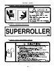
SECTION 1 - SAFETY SAFETY DURING TRANSPORT 1. Ability to safely operate the Summers Superroller is determined by both tractor horsepower and weight. The minimum tractor weight for operating this implement is 20,000 lbs. Minimum tractor engine horsepower is 180. Dual tires or single tires set at maximum width are required for safe operation of Land Roller. 2. ONLY TOW at a safe speed – 20 MPH MAXIMUM. Use caution when making corners and meeting traffic. 3.
SECTION 1 - SAFETY 3. PN 8Z0087 – DECAL FOR PINCH POINT HAZARD 4. PN 8Z0132 – SUPERROLLER ID DECAL 5.
SECTION 1 - SAFETY 6. PN 8Z0800 – AMBER REFLECTOR 7. PN 8Z0805 – RED-ORANGE REFLECTOR 8. PN 8Z0810 – RED REFLECTOR SAFETY LIGHT OPERATION The Summers Safety Light Kit is equipped with a 7 pin connector which meets SAE J560 specification. To protect 7 pin connector, store in dust cap (8K8067) when not attached to towing vehicle. On most towing vehicles WITHOUT brake lights: Amber lights will turn on with flashers or turn signals. Red lights will turn on with parking, road or field lights.
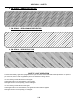
8Z0805 8Z0087 1-5 8Z0800 8Z0075 8Z0087 8Z0800 8Z0132 8Z0276 8Z0079 WARNING STICKERS ARE THE SAME ON THE RIGHT SIDE OF MACHINE. 2/27/2013 9LR0410.
SECTION 1 - SAFETY 1-6
SECTION 2 - ASSEMBLY GENERAL ASSEMBLY SAFETY PRACTICES 1. READ AND UNDERSTAND Operator’s Manual before assembly of machine. 2. If machine is to be assembled INDOORS, check that exit door is a MINIMUM OF 14’ WIDE and a MINIMUM of tractor height. 3. Reference to “RIGHT” and “LEFT” is determined when machine IS VIEWED FROM THE REAR. 4. Reference to “FORWARD” means TOWARDS THE TRACTOR. 5. Reference to “REAR” means AWAY FROM THE TRACTOR.
SECTION 2 - ASSEMBLY GENERAL SAFETY PRACTICES BLOCK UP ANY RAISED PART of the machine. Be sure machine is stable after blocking. YOU ARE RESPONSIBLE for the safe assembly of the machine. ALWAYS INSPECT LIFTING CHAINS AND SLINGS for damage or wear. DO NOT ALLOW CHILDREN or other unauthorized persons within the assembly area. BE SURE LIFTING DEVICE IS RATED TO HANDLE THE WEIGHT.
SECTION 2 - ASSEMBLY Main Frame Roller Installation (Instructions for 41’, 46’ & 53’) (NOTE: 41’ shown in drawings) MF1. Position 8P4211 on a flat even surface; block the roller to avoid unexpected movement. CAUTION: The 11’ roller weighs 3300 lbs., use extreme care when moving rollers and frame components. NOTE: An H has been stamped onto one end of each roller. Position the center roller with the H to the left. All other rollers should have the H positioned to the center of the machine. MF2.
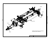
SECTION 2 - ASSEMBLY Hitch Installation H1. Position hitch as shown in Figure 2; install the pins and hardware shown in Figure 2. IMPORTANT Always install the pins with the cross hole towards the outside. Pay attention to the orientation of the cross hole in the pin to the cross hole in the bushing on the main frame, only drive the pin in far enough to line up the holes, install the fasteners shown in Figure 2. H2. Install the jack stand and pin. H3.
8K9106 Figure 2 8D9108 1/4 X 2" RP 8X0327 1 1/4" FW 8P0510 8P7140 8D9108 1/4 X 2" RP 8D9108 1/4 X 2" RP 8D1236 A 8K1620 2-5 8X0327 1 1/4" FW DETAIL A SCALE 1/20 8X0523 ROLL PIN 8A1004 5" HC 8X0203 3/8" FN 8P3910 8X0323 8X0304 5/8" FW 5/8" LW 8D8500 8X0253 NY-LOCK 5/8"-11NC 8K8067 8P7137 8A1157 3/8 X 4-1/16 X 7" 8T4385 8X0110 3/4 X 1-1/4" 8X0318 3/4" FW B 8X0281 NY-LOCK 1" 8X0309 1" LW DETAIL B SCALE 1/20 8D2470 8X0140 1 X 7" 8D0720 NOTE: DRUM OMITTED FROM THIS VIEW 5/8/2014 9LR04
SECTION 2 - ASSEMBLY Main Frame Transport Frame Installation T1. Loosely position 8T4100 on the main frame and affix the hardware associated with 8T4100. Do not tighten the fasteners. 8T4100 should always be positioned as shown, with the offset gap to the inside. 5 0''4&5 ("1 50 */4*%& 2/28/2013 9LR6242.iam/8T4101 OFFSET T2. Position the transport frame at the rear of the main frame, note the orientation of the cylinders clevis. Raise the transport frame so that pin 8T3640 can be driven into 8T4100.
Figure 3 2-7 8X0327 8D9108 1 1/4" FW 1/4 X 2" RP SECTION 2 - ASSEMBLY 8D0340 3/4 X 4-1/16 X 7-3/4" 8K9106 8X0242 NY-LOCK 1/2" N 8X0234 7/16" LNUT A 8T3640 8T4100 8X0306 3/4" LW 8P0510 8P7182 8X0265 3/4" LN DETAIL A SCALE 1 / 15 8X0044 7/16" X 3-1/2" 8X0072 1/2" X 3-3/4" 8K1105S 8K7430 3/19/2013 9LR0410.
SECTION 2 - ASSEMBLY Wing Installation The following instructions depict the right wing being installed on the machine. The left hand wing will follow the same procedure. P1W 1. Install the cast knuckle, 8C1805. The orientation of the knuckle is extremely important. Installing the knuckle in the wrong orientation will not allow the wings to fold properly. Structural damage may occur if the knuckle is installed incorrectly and the machine is unfolded. Install the pins and hardware as shown.
SECTION 2 - ASSEMBLY SECTION 2 - ASSEMBLY Figure 4 8X0234 7/16" LNUT 8X0320 3/8" FW 8X0045 7/16" X 4-1/2" 8X0302 7/16" LW B 8K1660 8C1805 DETAIL B SCALE 1/14 8X0045 7/16" X 4-1/2" 8R6040 8P7400R - 41' (SHOWN) 8P7410R - 53' 8P7405R - 46' A 8X0320 3/8" FW 8K1660 8P0306 8D9108 1/4 X 2" RP 8X0302 7/16" LW 8X0234 7/16" LNUT 8K9102 8P4215 - 41' (SHOWN) 8P4217 - 46' 8P4220 - 53' DETAIL A SCALE 1/14 3/9/2012 2-9 8P7170 9LR0410.
SECTION 2 - ASSEMBLY SECTION 2 - ASSEMBLY Figure 5 8P7195 8X0261 3/4" LN 8C0532HD 8L4628 P1W6. Install the hubs on 8P7165 as shown in Figure 5. Attach with the shown hardware and tighten. 8X0281 NY-LOCK 1" 8D9095 8X0261 3/4" LN 8X0115 3/4 X 3-1/2" Figure 4. Install snap rings on each roller shaft. Ensure that the roller is centered in the bearings and tighten the set screws. 8X0285 1 1/2" N DETAIL B SCALE 1 / 10 8X0414 8P7320 8J4600 P1W7.
SECTION 2 - ASSEMBLY SECTION 2 - ASSEMBLY Figure 6 8X0064 CRG 1/2 X 1-1/2" 8P7024 (25") 8X0246 1/2" FN 8P7025 (40") DETAIL A SCALE 1/10 8P7024 (25") B NOTE ORIENTATION OF CLIPPED CORNERS 8P6990 (90") 41' 8P7010 (105") 46' A 8P7090 (126") 53' DETAIL B SCALE 1/10 3/19/2013 2-11 9LR0410.
SECTION 2 - ASSEMBLY SECTION 2 - ASSEMBLY NOTE: MAIN LIFT CIRCUIT (RED) PLUMBED SO THAT ALL BASE ENDS OF CYLINDERS CONNECTED, ALL ROD ENDS OF CYLINDERS CONNECTED.
SECTION 2 - ASSEMBLY Hydraulic Installation H1. Install Hydraulic components as shown on Page 2-12. A. Leave enough slack at all pivot points to allow folding machine without stretching or pinching hydraulic hoses. B. Secure hoses with nylon ties and clamps provided. Do not over tighten clamps. H2. Make sure all hoses are routed the same on each side of the machine. H3. Secure hose with the provided clamps and hardware, use nylon ties where needed. Wiring Installation W1.
8K8095A RED LIGHT 8L0258 5/16X1-1/2X2-1/2" 8K8015 8K8090A 8Z0805 8L0258 5/16X1-1/2X2-1/2" DETAIL C 8X0203 3/8" FN 8K8030A MODULE-ENHANCER C A B 2-14 8X0440 8X0402 DETAIL A 8K8070B (MAIN HARNESS) 8S1126 8S1120 8K8200 8A1156 3/8 X 4-1/16 X 5" 3/19/2013 8X0202 3/8" LN DETAIL B 9LR0410.iam/SAFETY LIGHTS SECTION 2 - ASSEMBLY 8P7310 8K8080A (EXT.
SECTION 3 – OPERATION LAND ROLLER OPERATION SAFETY 1. READ AND UNDERSTAND Operator’s Manual before using machine. Review at least annually thereafter. 2. VERIFY all safety devices and shields are in place before using machine. 3. KEEP hands, feet, hair and clothing away from moving parts. 4. STOP engine, place all controls in neutral, set parking brake, remove ignition key and wait for all moving parts to stop before servicing, adjusting, maintaining or unplugging. 5.
SECTION 3 – OPERATION INITIAL HOOKUP: 1. Make tractor to hitch connection with locking draw pin and safety chain. 2. Retract jack and rotate into storage position. 3. Plug Lockpin Cylinder hoses into desired tractor outlet, adjust hydraulic flow rate to 35% of maximum. Insure that tips and couplers are CLEAN. 4. Plug Lift Cylinder hoses into desired tractor outlet, adjust hydraulic flow rate to 35% of maximum. 5.
SECTION 3 – OPERATION STEPS REQUIRED TO UNFOLD FROM TRANSPORT TO FIELD POSITION: 1. WARNING: Land Roller must be attached directly to tractor drawbar and not an intermediate towed vehicle or implement. Loss of control could result causing serious injury or death to you or others. Never tow this implement with less than an 20,000 lb. vehicle 2. Ability to safely operate the Summers Land Roller is determined by both tractor horsepower and weight.
SECTION 3 – OPERATION LAND ROLLER FIELD OPERATION: 1. Choose an operating speed which achieves desired results. Operating at over 7 MPH will decrease effectiveness and increase chance of immovable rocks denting roller tube. Denting of roller tube is NOT covered by warranty. 2. Slow down for turns. Because of the weight of the roller turning at high speeds may cause the tractor to “fish tail”. Control will be more easily maintained at slow rates of turns.
SECTION 3 – OPERATION TRANSPORTING LAND ROLLER: 1. If Land Roller is in Field Position, follow “Steps Required to Fold Land Roller from Field to Transport Position”, page 3-4. 2. Ability to safely operate the Summers Superroller is determined by both tractor horsepower and weight. The minimum tractor weight for operating this implement is 20,000 lbs. Minimum tractor engine horsepower is 180. Dual tires or single tires set at maximum width are required for safe operation of Land Roller. 3.
SECTION 3 – OPERATION UNHOOKING LAND ROLLER FROM TRACTOR IN TRANSPORT POSITION: 1. NEVER unhook Land Roller if positioned between Field and Transport Position. 2. DO NOT ALLOW ANYONE TO WORK UNDER LAND ROLLER. 3. Choose a very firm level surface. 4. Block tires to prevent movement after hitch pin is removed. 5. Check that hitch pin is not bound with sideways or front to back pressure. If hitch pin is not free, carefully reposition tractor 6.
SECTION 4 – MAINTENANCE MAINTENANCE SAFETY 1. STOP engine, place all controls in neutral, set parking brake, remove ignition key and wait for all moving parts to stop before servicing, adjusting or maintaining. 2. BE CAREFUL when working around high pressure hydraulic system. 3. ALWAYS make sure that Land Roller is lowered into field position, it is blocked to prevent movement and pressure is relieved from hydraulic circuits before servicing. 4. USE EXTREME CARE when making adjustments. 5.
SECTION 4 – MAINTENANCE STORAGE 1. 2. 3. 4. 5. Follow steps outlined in “UNHOOKING LAND ROLLER FROM TRACTOR IN FIELD POSITION”. Clean and remove all excessive dirt and grease from Land Roller. Grease all zerks. To prevent rusting, repaint any areas that have been worn, chipped or scratched. Apply grease* to any exposed part of cylinder shafts. *NOTE: Before returning Land Roller into service, all grease must be removed from cylinder shafts to prevent damage to seals.
SECTION 5 – PARTS OWNER REGISTER INFORMATION, LOCATED AT THE BEGINNING OF THIS MANUAL, MAY BE NEEDED WHEN ORDERING PARTS (SERIAL NUMBER IS LOCATED BY THE FRONT OF THE HITCH).
SNAP RING IS OPTIONAL. DUE TO MANUFACTURING TOLERANCE THE SNAP RING MAY NOT BE NEEDED. 8P7122 8X0265 3/4" LN 8R8010 8X0306 3/4" LW DETAIL A SCALE 1 / 10 8X0111 3/4" X 2-1/2" NOTE ORIENTATION OF GREASE ZERK BLOCK FRAME AT ARROWS 8P4211 AFTER DRUM IS INSTALLED PLACE STANDS AT THE 4 LOCATIONS SHOWN TO STABILIZE FRAME ↑ ↑ A 3/8/2012 9LR0410.
8D9108 1/4 X 2" RP 8K9106 8X0327 1 1/4" FW 8P0510 8P7140 8D9108 1/4 X 2" RP 8D9108 1/4 X 2" RP 8D1236 A 8K1620 5-3 8X0327 1 1/4" FW DETAIL A SCALE 1/20 8X0523 ROLL PIN 8A1004 5" HC 8X0203 3/8" FN 8P3910 8X0323 8X0304 5/8" FW 5/8" LW 8D8500 8X0253 NY-LOCK 5/8"-11NC 8K8067 8P7137 8A1157 3/8 X 4-1/16 X 7" 8T4385 8X0110 3/4 X 1-1/4" 8X0318 3/4" FW B 8X0281 NY-LOCK 1" 8X0309 1" LW DETAIL B SCALE 1/20 8D2470 8X0140 1 X 7" 8D0720 NOTE: DRUM OMITTED FROM THIS VIEW 5/8/2014 9LR0410.
5-4 8X0327 8D9108 1 1/4" FW 1/4 X 2" RP SECTION 5 – PARTS 8D0340 3/4 X 4-1/16 X 7-3/4" 8K9106 8X0242 NY-LOCK 1/2" N 8X0234 7/16" LNUT A 8T3640 8T4100 8X0306 3/4" LW 8P0510 8P7182 8X0265 3/4" LN DETAIL A SCALE 1 / 15 8X0044 7/16" X 3-1/2" 8X0072 1/2" X 3-3/4" 8K1105S 8K7430 3/19/2013 9LR0410.
SECTION 5 – PARTS 8X0234 7/16" LNUT 8X0320 3/8" FW 8X0045 7/16" X 4-1/2" 8X0302 7/16" LW B 8K1660 8C1805 DETAIL B SCALE 1/14 8X0045 7/16" X 4-1/2" 8R6040 8P7400R - 41' (SHOWN) 8P7410R - 53' 8P7405R - 46' A 8X0320 3/8" FW 8K1660 8P0306 8D9108 1/4 X 2" RP 8X0302 7/16" LW 8X0234 7/16" LNUT 8K9102 8P4215 - 41' (SHOWN) 8P4217 - 46' 8P4220 - 53' DETAIL A SCALE 1/14 3/9/2012 5-5 8P7170 9LR0410.
SECTION 5 – PARTS 8X0285 1 1/2" N 8P7195 8X0261 3/4" LN 8C0532HD 8X0281 NY-LOCK 1" 8D9095 8X0261 3/4" LN 8X0115 3/4 X 3-1/2" DETAIL B SCALE 1 / 10 8L4628 8C0532HD 8X0414 8P7320 8J4600 8K1620 8X0414 8X0138 1 X 5-1/2" 8X0122 3/4 X 4 1/2" 8K1620 8X0283 1 1/4" JN 8X0098 5/8 X 3.5" A 8P7197 8X0251 5/8 JN 8P7155 B 8X0222 1/4" LN 8X0005 1/4" X 3-3/4" 8X0242 NY-LOCK 1/2" N 8X0380 3.06"IDX4.
8Z0805 8Z0087 5-7 8Z0800 8Z0075 8Z0087 8Z0800 8Z0132 8Z0276 8Z0079 WARNING STICKERS ARE THE SAME ON THE RIGHT SIDE OF MACHINE. 2/27/2013 9LR0410.
HUB AND AXLE COMPONENTS Assembly Notes: A. Before towing machine, pack wheel bearings and fill 1/2 of hub cavity with high quality bearing grease. B. Tighten axle nut to 45 ft.-lbs, loosen nut until first slot is aligned with hole in axle, install cotter pin and bend to retain. Legend: SMC Part Number INDUSTRY Part Number or Size H211 1. SEAL 2. INNER BEARING 3. INNER RACE 8G8220 8G8217 8G8230 4. OUTER 5. HUB ASSY RACE 8G8230 8G8211 6. WHEEL STUD 7.
SECTION 5 – PARTS SECTION 5 – PARTS NOTE: MAIN LIFT CIRCUIT (RED) PLUMBED SO THAT ALL BASE ENDS OF CYLINDERS CONNECTED, ALL ROD ENDS OF CYLINDERS CONNECTED.
SECTION 5 – PARTS 8K8020 8K8095A RED LIGHT 8L0258 5/16X1-1/2X2-1/2" 8K8015 8K8090A 8Z0805 8L0258 5/16X1-1/2X2-1/2" DETAIL C 8X0203 3/8" FN 8P7310 8K8030A MODULE-ENHANCER 8K8080A (EXT. HARNESS) C A B 8X0440 8X0402 DETAIL A 8K8070B (MAIN HARNESS) 8S1126 8S1120 8K8200 8X0202 3/8" LN 8A1156 3/8 X 4-1/16 X 5" 3/19/2013 DETAIL B 9LR0410.
SUMMERS MFG. CO., INC. 3/21/12 INSTALLATION AND OPERATION INSTRUCTIONS FOR 8K1800 ACRE METER FOR SUPERROLLER 1. If Roller Shaft is not tapped, weld ½”-20 UNF nut at center of left pivot shaft of middle roller. Position external taper of nut toward shaft. Insure that threads are not damaged by weld heat or spatter. Allow weld to cool. 2. Attach Acre Meter with ½” lock washer. Tighten to 260-390 in-lbs. * For accurate logging of acres, it is important that meter is mounted concentrically on roller shaft.
Stock Code 8A1155 8A1156 8A1157 8A4048 8A4050 8A4052 8A4054 8C0270 8C0432 8C0532HD 8C1700 8C1710 8C1718 8C1720 8C1736 8C1740 8C1755 8C1760 8C1780 8C1900 8D0330 8D0340 8D0350 8D0720 8D0722 8D0724 8D0730 8D0745 8D2440 8D2460 8D2470 8D2730 8D3150 8D3152 8D3212 8D5212 8D5219 8D8490 8D8500 8D8521 8D8522 8D8523 8D9108 8D9109 8D9110 8G2281 8G2282 8G2283 8G2284 8G2285 8G2286 8G8010 8G8020 8HD0200 8J5100 8J5102 8J5110 8J5150 8J5152 Description U-BOLT 3/8 X 6-1/16 X 5” SQ U-BOLT 3/8 X 4-1/16 X 5” SQ U-BOLT 3/8 X 4-1
Stock Code 8K8070B 8K8075A 8K8080A 8K8088 8K8090 8K8090A 8K8092 8K8095 8K8095A 8K8105A 8K8200 8K8202 8K8210 8K8220 8K9102 8K9106 8L0252 8L0256 8L0258 8L0260 8L0262 8L0266 8L0268 8L4628 8N2012 8N2024 8N2036 8N2050 8N2054 8N2060 8N2072 8N2076 8N2088 8N2096 8N2110 8N2120 8N2135 8N2160 8N2190 8N2210 8N2248 8N2250 8N2360 8N2400 8N2410 8N3018 8N3028 8N3035 8N3048 8N3060 8N3070 8N3084 8N3096 8N3124 8N3136 8N3150 8N3156 8N3160 8N3180 Description MAIN HRNSS 7PNLNG W/BRAKE 09EXT HRNSS NONDRAWBR DTSCH 07EXT HRNSS DRA
Stock Code 8P7030 8P7040 8P7050 8P7070 8P7140 8P7150LB 8P7150RB 8P7160L 8P7160R 8P7165 8P7 8P7190B 8P7200 8P7250 8P7255 8P7310 8P7400L 8P7400R 8P7405L 8P7405R 8P7410L 8P7410R 8R8005 8R8010 8S0280 8S0295 8S0315 8S0319 8S0330 8S0340 8S0345 8S0358 8S0360 8S1120 8S1124 8S1126 8S2990 8T3300 8X0000 8X0000B 8X0001 8X0002 8X0003 8X0004 8X0005 8X0006 8X0007 8X0008 8X0009 8X0010 8X0011 8X0013 8X0014 8X0015 8X0016 8X0017 8X0019 8X0020 8X0021 Description SCRAPER 42” ROLLER 34” 09SCRAPER 36” ROLLER 68” 09SCRAPER 42” RO
Stock Code 8X0116 8X0117 8X0118 8X0118A 8X0119 8X0120 8X0121 8X0122 8X0123 8X0125 8X0128 8X0130 8X0132 8X0133 8X0138 8X0139 8X0140 8X0141 8X0142 8X0143 8X0145 8X0149 8X0150 8X0201 8X0202 8X0203 8X0204 8X0205 8X0210 8X0211 8X0212 8X0218 8X0220 8X0222 8X0223 8X0232 8X0234 8X0240 8X0242 8X0244 8X0246 8X0250 8X0251 8X0253 8X0256 8X0259 8X0260 8X0261 8X0264 8X0265 8X0266 8X0268 8X0269 8X0270 8X0274 8X0277 8X0278 8X0280 8X0281 Description BOLT 3/4-10NC X 6” GR5 YZ BOLT 3/4-10NC X 7” GR5 YZ BOLT 3/4-10NC X 4” GR5
Stock Code 8X0727 8X0728 8Z0070 8Z0079 8Z0087 8Z0101 8Z0104 8Z0106 8Z0132 8Z0202 8Z0276 8Z0278 Description ZERK 1/8” MPT 90 DEG YZ ZERK STANDOFF 1/8” NPT X 3” DECAL “SUMMERS” 1.25 X 6” DECAL “SUMMERS” 5 X 20” DECAL”WARNING”PINCH POINT03DECAL”SUMMERS”M94/04/06 2.25X9 DECAL”WARNING”LNDROLLER HITCH DECAL”DANGER”LNDRLLR TRNSPRT DECAL ID SUPERROLLER 05DECAL”SUMMERS” 4 X 13.
History of Summers Manufacturing Co., Inc. 1965 – Summers Manufacturing is founded by Harley Summers, who purchases patent rights for Goebel truck and pickup hoists from the Goebel Brothers of Lehr, ND. These hoists, produced in Harley Summers’ blacksmith shop the first year, were distributed nationwide by a Cincinnati, Ohio, dealer. With increasing sales, the company soon outgrows the small shop. Summers wins the Herman harrow contract, beginning the company’s Herman culti-harrow line.
Model 700 Rock Picker Superrollers Superchisel Coulter-Chisel Disk-Chisel Hydraulic Fold Coil Packer & Hydraulic Fold Rolling Chopper Mounted Harrows Rolling Choppers Superharrow Plus & Superharrow 2650 Diamond Disk & 2510 DT Supercoulter Plus © Copyright 2013 Summers Manufacturing Co., Inc. All Rights Reserved Rolling Baskets Ultra & Ultimate NT Supersprayer 11-1-12 To find a dealer near you check out our website - www.summersmfg.