
User guide


SECTION 2 - ASSEMBLY
-70
8/27/2014
9LR3042.iam/
21 1/2"
21 1/2"
8P6110
8X0044
7/16" X 3-1/2"
8D0350
3/4"X4-1/16"X10"
8X0234
7/16" LNUT
8X0260
3/4" N
8T4100
8T3640
8P6105
8X0072
1/2" X 3-3/4"
8X0242
NY-LOCK 1/2" N
8K1105S
8K7042
8P6110
PRE-ASSEMBLE
BEFORE
ATTACHING TO
CENTER FRAME
TOWARDS
TRACTOR
8P6110S
8X0306
3/4" LW
8K7123
8X0133
7/8 X 3"
8X0307
7/8" LW
8X0268
7/8" N
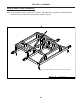
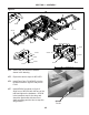
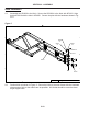
Wheel and Pivot Arm Intallation.
WP1. Locate 8P6110 and 8P6110S and install hub assemblies as shown in Figure 5. Secure hub
assemblies with the hardware shown.
WP2. Install two wheels on each assembly. Torque wheel nuts to 240 FT-LB
WP3. Installtwo8T4100asshowningure.Looselyattachtotheframewith8D0350,lockwash-
ers and nuts. This will allow them to be moved and positioned when attached the pivot
arms.
WP4. PositionthePivotArmAssemblyandwheelsasshowningure.TheCenterofthearm
should be positioned to the dimension shown.
WP5. Installpin8T3640,alignholeinpinwiththeholein8T4100andsecurewiththehardware
shown.
WP6. TightenhardwarethatwasinstalledinWP3.(Makesurethecenterofthearmispositioned
to the dimension shown in Figure 5.)
WP7. RepeattheabovestepsfortheotherPivotArm.Refertothedrawingtoensuretheproper
pivot arm is installed in the correct location.
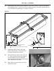
WP8 Looselyinstalltwo8P6215inthelocationsshowninFigure6,securewiththehardware
shown.
2-8
Figure 5