Manufactured By: England’s Stove Works, Inc. PO Box 206 Monroe, VA 24574 INSTALLATION & OPERATION MANUAL 25‐CB120 55‐SHPCB120 55‐TRPCB120 05/2016 CAUTION PLEASE READ THIS ENTIRE MANUAL BEFORE INSTALLATION AND USE OF THIS PELLET FUEL‐BURNING APPLIANCE. KEEP CHILDREN, FURNITURE, AND ALL COMBUSTIBLES AWAY FROM ANY HEATING APPLIANCE. SAFETY NOTICE FAILURE TO FOLLOW THESE INSTRUCTIONS CAN RESULT IN PROPERTY DAMAGE, BODILY INJURY OR EVEN DEATH.
IMPORTANT: IF YOU HAVE A PROBLEM WITH THIS UNIT, DO NOT RETURN IT TO THE DEALER. CONTACT TECHNICAL SUPPORT @ 1‐800‐245‐6489 Tamper Warning: This wood heater has a manufacturer‐set minimum low burn rate that must not be altered. It is against federal regulations to alter this setting or otherwise operate this wood heater in a manner inconsistent with operating instructions in this manual.
TABLE OF CONTENTS Introduction Introduction ....................................... 4 Specifications Heating Specifications ....................... 5 Dimensions ........................................ 5 EPA Compliance ................................. 5 Installation Installation Overview................... 6 Clearances to Combustibles.........7 Venting Introduction................... 8 Venting Guidelines....................... 8 Additional Venting Information....
INTRODUCTION Thank you for purchasing this fine product from England’s Stove Works! England’s Stove Works was started, and is still owned by, a family that believes strongly in a “Do It Yourself” spirit; that’s one reason you found this product at your favorite “Do It Yourself” store. We intentionally design and build our stoves so that any homeowner can maintain their stove with basic tools, and we’re always more than happy to help you do the job as easily and as inexpensively as possible.
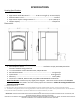
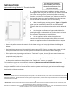
SPECIFICATIONS Heating Specifications Approximate Pellet Burn Rate**………………0.78 to 1.72 kg/hr (1.72 to 3.8 lbs/hr) Maximum Burn Time**………………………………………………………………………..72 hours Approximate Square Footage Heated***…….………………………….up to 2,200 sq. ft. Hopper Capacity………………………………………………………………………….…..120 pounds Dimensions EPA and Safety Compliance Specifications EPA Compliance Status ……......................................... Certified to comply with 2020 particulate emission standards using pellet fuel.
INSTALLATION Installation Overview When choosing a location for your new stove, there are a multitude of factors that should be taken into account before beginning the installation. 1. Traffic Patterns – To help prevent accidents, the stove should be placed in a location where it is out of the way of normal travel through the home. 2. Heat Flow and Efficiency – When deciding on a location for the stove, consider the way heat moves throughout your home.
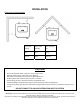
INSTALLATION Clearances to Combustibles Unit to Side Wall (A) Unit to Rear Wall (B) Unit to Corner (C) 10 in. 0 in. 10 in. 254 mm 0 mm 254 mm CAUTION Unit can be very HOT while in operation. Keep children away. Supervise children in the same room as this appliance. Alert children and adults to the hazards of high temperatures. Do NOT operate with protective barriers open or removed. Keep clothing, furniture, draperies and other combustibles away.
INSTALLATION Venting Introduction This pellet stove operates on a negative draft system, which pulls combustion air through the burn pot and pushes the exhaust air through the vent pipe and out of the building. This unit must be installed in accordance with the following detailed descriptions of venting techniques; not installing the stove in accordance with the details listed here can result in poor stove performance, property damage, bodily injury or death.
INSTALLATION Additional Venting Information Do not mix and match components from different pipe manufacturers when assembling your venting system (i.e. Do NOT use venting pipe from one manufacturer and a thimble from another). We require a minimum vertical rise of 36 in. (3 ft.) of pipe to create natural draft in the system. This helps evacuate smoke from the stove in the event of a power failure or combustion blower failure. Venting systems 15.0 ft. or shorter may be composed entirely of 3.0 in.
INSTALLATION Approved Venting Method 1: Through the Wall For high altitude installations (above 4,000 ft.), the vent pipe should be increased from 3‐inch (3”) to four‐inch (4”). Generally the simplest installation method, venting through the wall using our AC‐3000 kit, AC‐33000 if Canada (or similar venting system) is also the preferred venting method.
INSTALLATION Approved Venting Method 2: Through the Ceiling For high altitude installations (above 4,000 ft.), the vent pipe should be increased from 3‐inch (3”) to four‐inch (4”). Venting through the ceiling/roof may be the only feasible venting option in some cases and is a factory recommended installation. When installing any venting system, Type L or Type PL pipe must be used and all clearances to combustibles listed by the pipe manufacturer must be strictly adhered to.
INSTALLATION Approved Venting Method 3: Existing Chimney System For high altitude installations (above 4,000 ft.), the vent pipe should be increased from 3‐inch (3”) to four‐inch (4”). Using an existing masonry or factory built chimney for venting is the only other acceptable method for venting this pellet unit. Use Type L or Type PL venting pipe until entering the existing chimney.
For high altitude installations (above 4,000 ft.), the vent pipe should be increased from 3‐inch (3”) to four‐inch (4”). INSTALLATION Mobile Home Installation The England’s Stove Works, Inc. outside air kit MUST be used for installation of this unit in a mobile home. Please see the “Outside Air” section on page 15 for more information regarding outside air connections. The outside air inlet must be kept clear of leaves, ice and other debris.
VENT TERMINATION CLEARANCES A) Min. 4‐ft clearance below or beside any door or window that opens. B) Min. 1‐ft clearance above any door or window that opens. C) Min. 2‐ft clearance from any adjacent building. D) Min. 7‐ft clearance from any grade when adjacent to public walkways. E) Min. 2‐ft clearance above any grass, plants, or other combustible materials. F) Min. 3‐ft clearance from a forced air intake of any appliance. G) Min. 2‐ft clearance below eaves or overhang. H) Min.
OUTSIDE AIR HOOK‐UP The use of outside combustion air is mandatory on this pellet stove. The outside air connection pipe protrudes from the lower rear center of the stove; use the included outside air kit to attach your stove to outside combustion air. Instructions and all the parts needed to make the outside air connection to your pellet stove are included with the outside air kit.
FLOOR PROTECTION This pellet stove requires a non‐combustible floor protector if the stove is to be installed on a combustible floor. If the floor the stove is to be installed on is already non‐combustible (i.e. a concrete floor in a basement) and has an R value equal to or higher than .2, no floor protection is needed (although a decorative floor protector can still be used for aesthetic reasons).
DAILY OPERATION Getting Started Check to see that the hopper is clean and free from foreign materials. Be sure to connect this unit to a working outlet; we recommend using a surge protector to help protect the electronic components from damage. BEFORE your first fire, dry run your unit (no pellet fuel in the hopper) for twenty minutes; pressing the “ON” button with the unit plugged in will initiate the dry run.
Daily Operation Notes Only high quality, Premium Grade ¼” (.25 in.) diameter wood pellets should be used in this stove. Using low grade wood pellets with high ash content OR wood pellets with a high moisture content can cause the burn pot to fill with ash at a more rapid pace and can cause intervals between periodic maintenance to become significantly shorter. Please read the “Maintenance” section of this manual thoroughly to understand how fuel selection affects stove operation, maintenance and cleaning.
CONTROL BOARD SETTINGS Manual/Automatic Mode Automatic Mode Your stove will arrive from the factory programmed in automatic mode. First, make sure the thermocouple wire is resting loosely outside the back of the stove (so that it is reading the air temperature) in a safe location where it can’t be damaged. It should not rest directly on the floor, or it will pick up the floor temperature. The thermocouple wire is the “room temperature heat sensor” whereby the control board will read the room temperature.
Setting Stove in Automatic Mode o To set the stove back into automatic mode, press the down arrow and the up arrow button simultaneously. This will toggle the stove to Automatic Mode. o While in Automatic Mode, the stove board will display the Set Temperature. o The control board on this stove allows the user to adjust the heat output and convection blower speed, turn the unit on and off, and test components for function (more on diagnostic mode later).
ERROR CODES Error codes are alphanumeric codes that will appear in the Heat Range and Blower Speed window of the Control Board if the unit experiences an abnormal condition. Error codes are the control board’s way of telling the user that something isn’t operating correctly within the stove, and that the unit should be carefully inspected before reigniting. See the “Trouble‐Shooting Guide,” page 30, for additional information on error codes.
POWER FAILURE If the power to the unit is interrupted for approximately three minutes or less, the unit will resume operation when power is restored according to the following table: Unit’s State Before Power Loss State When Power Returns ON Warmup Warmup Warmup Shut‐Down Shut‐Down OFF OFF If the power is interrupted for more than (approximately) three minutes, the unit will be “OFF” when power returns. IMPORTANT – Do NOT open the hopper lid or the door to the unit during power outage.
*Failure to properly clean your stove can cause poor performance and possibly a burn back!* DAILY MAINTENANCE Disposal of Ashes – Ashes should be placed in a metal container with a tight fitting lid. The closed container of ashes should be placed on a noncombustible floor or on the ground, well away from all combustible materials, pending final disposal.
Because of the open design of the firebox, the majority of the ash will be on either side of the cradle. Open the door of the stove and use an old paint brush or putty knife to move ash from around the burn pot and into the open areas beside the cradle. Using the cleaning tool provided, remove any deposits left in the burn pot, being careful to remove them from the burn pot and not allow them to filter down into the cradle area.
WEEKLY MAINTENANCE Baffle Removal As with any maintenance concerning this unit, be sure the unit is “OFF,” has completed the Shut‐Down cycle, and is completely cool BEFORE beginning. Be aware that metal parts in the firebox can remain HOT long after the fire has gone out and EVEN after the Shut‐Down cycle is complete. Always use extreme caution when handling potentially hot stove parts, even if you think they should be cold.
Be aware that metal parts in the firebox can remain HOT long after the fire has gone out and EVEN after the Shut‐Down cycle is complete. Always use extreme caution when handling potentially hot stove parts, even if you think they should be cold. Monthly maintenance should include the steps listed in this section AS WELL AS the steps listed in the “Daily Maintenance” and “Weekly Maintenance” section.
YEARLY MAINTENANCE Important Notes As with any maintenance concerning this unit, be sure the unit is “OFF,” has completed the Shut‐Down cycle, and is completely cool BEFORE beginning. Be aware that metal parts in the firebox can remain HOT long after the fire has gone out and EVEN after the Shut‐Down cycle is complete. Always use extreme caution when handling potentially hot stove parts, even if you think they should be cold.
YEARLY MAINTENANCE Exhaust Blower Cleaning Although the exhaust blower and blower housing were designed to minimize ash build‐up, some fly‐ash will still accumulate there throughout the burning season. The amount and type of ash will depend on the type of pellets and venting system, but generally this accumulation will be mild.
YEARLY MAINTENANCE Cleaning Pellet Fines from the Hopper and Auger Depending on the type and quality of pellets burned in the stove, some accumulation of pellet fines and dust is possible in the hopper. The lowest part of the auger, near the back of the stove, is where most fines will accumulate. With the stove off, unplugged, completely cool and with the hopper empty, use a utility vacuum to remove the fines from the auger tube.
Trouble‐Shooting Guide WARNING: To avoid ELECTRICAL SHOCK always disconnect the unit from the power source BEFORE attempting any repair. If this guide does not correct the problem, call your local dealer or Technical Support at 1‐800‐245‐6489. Problem Auger not turning Smoke smell or dust in house Room blower not operating Exhaust blower not operating Lazy Fire Blown Fuse Cause 1. Bad auger motor. 2. Foreign matter jamming auger. 3. Vacuum sensor. 1. Improper exhaust connection. 1.
Unit Shuts Down in 15‐20 minutes with an "FS" code on control board. (Failed Start) 1. Loose thermal sensor. 2. Control board settings. 3. Failure to light pellets. "OT" Code on Control Board (OverTemp) 1. Check both sides of thermal sensor connection (exhaust blower and control board). 2. Start stove on minimum Heat Range 5 to ensure a good fire is started. 3. Check igniter for buildup or failure. 1. Convection (Room Air) blower failure. 1.
REPLACING COMPONENTS Auger Motor Before beginning any component replacement, be certain the unit is unplugged and thoroughly cooled down. Also, make sure the hopper is empty before attempting to remove or replace the auger motor assembly. Remove the back panel of the unit, using a 5/16” wrench. Before loosening any auger motor bolts, detach the wiring harness from the auger motor.
REPLACING COMPONENTS Convection Blower Before beginning any component replacement, be certain the unit is unplugged and thoroughly cooled down. Remove the rear panel (using a 5/16” wrench) and locate the convection blower. Detach the convection blower from the wiring harness before going any further. Loosen and remove the (4) 5/16” screws which hold the blower assembly to the stove; remove the blower assembly from the stove.
REPLACING COMPONENTS Combustion Blower Before beginning any component replacement, be certain the unit is unplugged and thoroughly cooled down. Remove the left side panel and locate the combustion blower. Disconnect the venting system from the exhaust blower, and disconnect the exhaust blower from the stove wiring harness. To remove the venting pipe, removal of the rear panel (using a 5/16” wrench) may be necessary. Remove all (5) screws which hold the exhaust blower to the exhaust blower tube.
REPLACING COMPONENTS Vacuum Switch Before beginning any component replacement, be certain the unit is unplugged and thoroughly cooled down. Remove the right side panel (see p. 42 for panel instructions). Locate the vacuum switch as shown in the diagram below. Disconnect the stove wiring harness and vacuum hose from the vacuum switch, taking note of where connections were made. Remove the (2) screws which hold the vacuum switch to the vacuum switch bracket, using a Phillips screw driver.
REPLACING COMPONENTS Igniter Before beginning any component replacement, be certain the unit is unplugged and thoroughly cooled down. Remove the rear panel of the unit, using a 5/16” wrench. Locate the igniter as shown in the diagram below. Disconnect the igniter wiring from the control board and use a 5/16” wrench to remove the two igniter retaining screws that fasten the assembly to the stove. Remove the assembly from the stove.
REPLACING COMPONENTS IMPROPER GASKET MAINTENANCE, INCLUDING FAILURE TO REPLACE GASKETS, CAN CAUSE AIR LEAKS RESULTING IN SMOKE‐BACKS. Gaskets 1. Door This unit comes with a ¾” rope gasket in the channel around the door opening that should be replaced at least once every year. To replace the door gasket (Part # AC‐ DGKHD), the old gasket must first be removed entirely — prior to adding the new adhesive, you may have to scrape the old cement from the channel.
REPLACING COMPONENTS Glass This unit has one ceramic glass panel (Part # AC‐G60) in the door; self adhesive window gasket is included with replacement windows purchased directly from England’s Stove Works. Never replace ceramic glass with tempered or any other type of glass and never operate this unit with cracked or broken glass.
REPLACING COMPONENTS Control Board *BEFORE REPLACING THE CONTROL BOARD BE SURE THE UNIT IS COOLED COMPLETELY AND UNPLUGGED.* The Control Board (Part # 25‐SSCB) is a digital read‐out board. To replace the control board, first unplug the power cord from the wall outlet. Remove the front face of the control board by pulling it forward. Once the board is apart, use a pair of needle nose pliers to disconnect the wiring harness, room sensor, heat sensor, hopper lid and vacuum switch connectors.
Vac Switch/ Hopper Lid Switch WIRING DIAGRAM Caution – Shock Hazard Press the “Off” button and let the appliance completely cool BEFORE unplugging the appliance and beginning any maintenance or component replacement. Risk of shock if appliance is not unplugged before service. 40 IMPORTANT! READ AND FOLLOW ALL INSTALLATION AND MAINTENANCE INSTRUCTIONS, INCLUDING CLEANING THE UNIT AS SPECIFIED, AND REPLACING GASKETS ANNUALLY, AND PARTS AS NEEDED.
HOPPER LID HINGES The hopper lid is attached to the top of the stove by two removable hinges. To remove the hopper lid hinges: Remove the (4) screws that hold each hinge in place, using a 5/16” socket. Re‐Install hinges in the reverse method. HOPPER LID HANDLE The hopper lid handle snaps into place in the opening in the hopper lid. To remove the hopper lid handle: Lift the hopper lid up (in the open position). Press up on the bottom of the handle and it will pop out of place.
SIDE PANELS The side panels are designed to hang onto the sides of the stove and can easily be removed to perform regular cleaning (and any maintenance that may need to be done in the back of the stove). To remove side panels: Loosen (DO NOT REMOVE) the (2) 5/16” screws that hold the side panel to rear of the stove. Grasp the panel and lift straight up until the tabs are removed from the side tracks and pull the panel towards you. Re‐install the side panels using the reverse of this method.
ILLUSTRATED PARTS DIAGRAM 43 IMPORTANT! READ AND FOLLOW ALL INSTALLATION AND MAINTENANCE INSTRUCTIONS, INCLUDING CLEANING THE UNIT AS SPECIFIED, AND REPLACING GASKETS ANNUALLY, AND PARTS AS NEEDED. ENGLAND’S STOVE WORKS IS NOT RESPONSIBLE FOR ANY DAMAGE OR INJURY INCURRED DUE TO NEGLECT, OR DUE TO UNSAFE INSTALLATION OR USAGE OF THIS PRODUCT. CALL TECHNICAL SUPPORT WITH ANY QUESTIONS.
REPLACEMENT PARTS LIST Part No BM‐1288 CU‐047042 PU‐076002B AC‐DGKHD PU‐HLSB CU‐VS 25‐SSCB 25‐SSWH AC‐HP AC‐MBSP AC‐SH1 AC‐SHN2 CA‐AC CA‐AMPP PU‐AFS PU‐CHSS PU‐HH PU‐VH AC‐GGK AC‐G60 AC‐SSGT AC‐HLH AC‐CBRB AC‐SSDTG CA‐SSD PU‐SSBP PU‐CBMG PU‐SSTCW PU‐SSACP PU‐BMTS PU‐BMTL Description Room Air Blower 2.4 RPM Auger motor CW Rotation Combustion Exhaust Blower(Neg) ¾” HD Door Gasket Hopper Lid Safety Switch .
AC‐CBTB PU‐SSDVD MU‐SSP01 PU‐CBEXCP PU‐RABMP CU‐RG PU‐RSP PU‐LSP PU‐SSHL PU‐MBS PU‐SSRP AC‐CT AC‐CMB AC‐CHSEP PU‐CBAWB Top Baffle (inside firebox) DVD Manual Exhaust Cover Plate (Qty.
IMPORTANT! READ AND FOLLOW ALL INSTALLATION AND MAINTENANCE INSTRUCTIONS, INCLUDING CLEANING THE UNIT AS SPECIFIED, AND REPLACING GASKETS ANNUALLY, AND PARTS AS NEEDED. ENGLAND’S STOVE WORKS IS NOT RESPONSIBLE FOR ANY DAMAGE OR INJURY INCURRED DUE TO NEGLECT, OR DUE TO UNSAFE INSTALLATION OR USAGE OF THIS PRODUCT. CALL TECHNICAL SUPPORT WITH ANY QUESTIONS.
LIMITED FIVE (5) YEAR WARRANTY From the date of purchase to the original owner. Model Numbers 25‐CB120 / 55‐SHPCB120 / 55‐TRPCB120 The manufacturer extends the following warranties: Five Year Period: 1. Carbon steel and welded seams in the firebox are covered for five (5) years against splitting. 2. The steel door and hinges are covered for five (5) years against cracking. One Year Period: 1.
*Some states do not allow the exclusion of limitations of incidental or consequential damages, so the above may not apply to you Procedure Purchaser must give notice of claim of defect within the warranty period and pay transportation to and from a service center designated by the manufacturer. The dealer from which the unit was purchased or the factory, at our option, will perform the warranty service.
Important Notice This registration information MUST be on file for this warranty to be valid. Please send this information within thirty (30) days from the original date of purchase. Use any of these three easy ways to send your warranty information in! Mailing Address England’s Stove Works, Inc. Technical support Department P.O.
IMPORTANT! READ AND FOLLOW ALL INSTALLATION AND MAINTENANCE INSTRUCTIONS, INCLUDING CLEANING THE UNIT AS SPECIFIED, AND REPLACING GASKETS ANNUALLY, AND PARTS AS NEEDED. ENGLAND’S STOVE WORKS IS NOT RESPONSIBLE FOR ANY DAMAGE OR INJURY INCURRED DUE TO NEGLECT, OR DUE TO UNSAFE INSTALLATION OR USAGE OF THIS PRODUCT. CALL TECHNICAL SUPPORT WITH ANY QUESTIONS.
WARRANTY REGISTRATION for England’s Stove Works® Purchaser Information* I. Purchased By (Name) II. Address III. City _________________________________________ ____________________________________________________ _______________________State________Zip Code IV. Telephone Number ____________ ___________________________________________ V. Email Address _______________________________________________ Dealer Information* VI. Purchased From _____________________________________________ VII.