
Installation Guide


8
SETUP INSTRUCTIONS
Before assembling your product, please take a few minutes to check the contents and become familiar with all the parts.
Site Preparation
• Select a level area, and completely remove all debris, twigs, stones, etc. DO NOT select an area under overhead electrical lines, trees, or within 15 feet of a house,
building, etc.
• The pool shall be located a minimum distance of 6ft (1.83m) from any electrical receptacle.
• All 125 volt, 15 and 20 ampere receptacles located within 20ft (6.0m) of the pool shall be protected by a ground fault circuit interrupter (GFCI).
The 20ft (6m) distance is measured via the shortest straight line distance the supply cord would follow without piercing a floor, wall, ceiling, doorway, window, or
other permanent barrier.
• Contact your local utilities, checking that no underground cables, telephone lines, gas lines, etc. run beneath the area you have selected.
WARNING - DO NOT overfill the pool and / or allow people to lay over or sit on pool wall - DOING SO CAN CAUSE PERMANENT INJURY!
DRAIN pool to the proper level after a heavy rain. The Maximum Water Level FILL LINE is printed on the pool liner.
TIP: It will be much easier to install your pool if you unfold it and let it lay in direct sunlight for about 2 hours prior to installation. This will help to ensure a
wrinkle-free fit because the pool material will be more pliable allowing it to form into shape during installation.
WARNING - IMPORTANT! SITE MUST BE LEVEL, STABLE, COMPACTED SOIL.
• The pool must be assembled on a smooth and level site of firm soil that is free of stones, gravel, sticks, blacktop, or other oil base compounds.
• Before setting up your pool, it is recommended that you clear the area of hardy grasses. Certain types of vigorous grasses such as St. Augustine and
Bermuda can grow through the liner. A ground cloth or tarp may be helpful in preventing this from occurring. Grass growing through the liner is not covered
under warranty.
• Do not install pool on a wooden deck or any type of wooden surface. You cannot use sand and/or uncompacted soil to provide a level surface for this pool;
it will only wash out.
• FAILURE TO FOLLOW ALL OF THESE INSTRUCTIONS WILL CAUSE POOL TO COLLAPSE AND WILL VOID THE WARRANTY!
EN
15. Go around and check all fittings, Push-buttons of O-Pins ,
Legs, and Beams are properly installed and secured in place.
Make sure the drain fitting is plugged securely and the
cap is in place (see Figure 10).
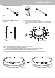
8. Insert the Vertical Legs 3 into the Leg Caps 6
(see Figure 3).
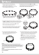
9a. Lay the pool liner on the ground (see Figure 4).
Note: Ensure the pool is between 10 to 21 feet away from any electrical outlets.
b. Place the connected parts around the pool liner, one set by one set near each
top sleeve.
10a. Slide a set of Horizontal Beam with T-Fitting into one sleeve of the liner (see Figure 5).
Note: 1. Leave the set with Easy Link T-Fitting to be installed LAST.
2. Make sure the vertical part of the T-Fitting faces down and away from the liner to avoid puncturing the liner.
b. Slide the next set of HorizontalBeam with T-Fitting into the sleeve beside the first set (see Figure 6).
Then, link the open end of the horizontal beam with the T-Fitting of the first set.
Press the push-button while sliding the parts together. Release the push-button for the parts to snap into place and lock tight.
Setup Instructions
1. Locate a level and flat area to set up the pool. Make sure the ground is free from sharp objects as they may puncture the pool.
2. Carefully unfold the pool liner in the area selected and inspect the seams for manufacturing defects.
3. It is recommended to let the pool sit out in direct sunlight for about 2 hours prior to installation (see TIP above).
4. LIFT the pool liner across the ground. DO NOT drag the liner from one location to another location.
5. Locate the pool so that the pump opening is 10 to 21 feet away from the electrical outlet.
6. Remove all parts from the packaging.
7. Connect each Horizontal Beam
2
with a T-Fitting
4
to form as a set (see Figure 1).
a) Press and hold the push-button below the T-Fitting, then connect it to one end of the Horizontal Beam.
b) Push the Horizontal Beam and T-Fitting together and release the push-button. It should snap into place and lock the T-Fitting and Horizontal Beam together.
If they are securely attached, you could feel the end of the O-Pin from the base of the Horizontal Beam.
c) Repeat Steps a) & b) for the other T-Fitting sets and one Easy Link T-Fitting
5
set (see Figure 2).
2
4
1
3
6
* Image for reference only
IMPORTANT: BEFORE ADDING WATER TO YOUR POOL YOU MUST INSTALL THE POOL WALL
FITTINGS OR ENTIRE FILTRATION SYSTEM FIRST. BEFORE ADDING WATER TO YOUR POOL
FOLLOW THE INSTRUCTIONS BELOW.
If your pool included openings or you are going to purchase a filter pump system, position the Suction & Return fitting locations so they are 10 to 21 feet
from the electrical outlet you plan to use for the pool pump.
If your pool came with Fittings - Install both the Suction and Return fittings to the pool wall before filling the pool.
1 2 3
4
5 6 7
ENEN
Please Note: The Black Rubber gasket (Gasket) should always be slid over
the threaded plastic suction or return fitting and be on the inside before the
fitting is placed through the pool wall to make a watertight connection.
Make sure to put on both the Water Cap and the Service Plug while you fill
your pool, or until you are ready to add a filtration system.
SUCTION FITTING RETURN FITTING
NOTE: For Sand Filter Pump / Cartridge Filter Pump
CP2000-C, please follow the Sand Filter Pump /
Cartridge Filter Pump CP2000-C owner’s manual to set up
the fitting. Please check the water pump’s instruction manual
for more instructions.
SFX SKIMMERPLUS FILTER PUMP
Pool
exterior
Pool
exterior
Pool interior
Pool interior
GasketService Plug
Return Fitting Suction Fitting
Washer
RF Nut
90° Elbow
Locking Ring
Return Fitting
Diverter
Horizontal Beam with T-Fitting Set
Horizontal Beam with Easy Link T-Fitting Set
11. Continue to slide the sets of Horizontal Beams and
T-Fittings through the remaining sleeves and link them
together to create the top frame structure.
12. Connect the set of Horizontal Beam and Easy Link T-Fitting
until you completed the full circle (see Figure 7).
13. Carefully slide the connected Vertical Legs 3 with Leg Caps 6
up through the belts that runs around the middle of the pool (see Figure 8a).
Tip: For smaller pools without a belt, slide the vertical legs up
through the sleeves on the pool wall (see Figure 8b).
CAUTION:
• Not following the steps above will make the pool fill unevenly and it may lean to
one side and collapse (see figure 11). Your pool should be straight and vertical to the ground.
If your pool is leaning at all, the ground may not be level and you will need to start over.
• Do not press the T-Fitting push button when filling the water in the pool or using the pool.
Only press the T-Fitting push button when the pool is empty.
WARNING!
FAILURE TO FOLLOW THE INSTRUCTIONS ABOVE WILL CAUSE POOL TO COLLAPSE
WILL VOID THE WARRANTY.
14. Look through the hole at the bottom of the T-fitting, as you insert the Vertical
Leg 3 with Leg Cap 6, rotate it until the buttons align with the holes and pop out,
locking the Vertical Leg in place (see Figure 9). Do this for all Vertical Legs.
Note: Each Vertical leg has a V-Shaped Spring Pin 7 pre-installed.
There is an extra pin included with your pool parts.
Tip: To avoid distortion during the assembly of the pool frame, connect one
Vertical Leg to every three T-Fitting so the frame can stand comfortably.
Connect the rest of the Vertical Legs to to finish assembling the pool.
Push-
Button
Pre-installed
O-pin
2
4
2
5
3
6
10’ - 21’
305 - 640 cm
3
3
16. Fill up the pool with about an inch (1”) [2.54 cm] of water. Stop filling
and smooth out all the wrinkles from the pool floor, working outwards
from the center, so that it fills evenly. Gently tug the Vertical Legs
outwards to ensure all legs are vertical and perpendicular to
the ground.
Note: If more than 1 to 2 inches (1”-2”) [2.54 cm-5.08 cm] of
water collects on any one side before the pool starts filling in the
center, the pool is not level enough, and must be corrected.
17. Install the filtration system as per its instruction manual.
18. Continue to fill the pool to approximately 8 inches (8”) [20.32 cm]
below the top rim.
Figure 1
Figure 2
Figure 3
Figure 4
Figure 5 Figure 6
Figure 7 Figure 8a Figure 8b
Figure 9
Figure 10
Figure 11
Pool exterior
Pool interior
SUCTION FITTING
Thrust Washer
Split Suction Fitting Lock Nut Solo Suction Fitting Lock Nut
Lock Nut Seal Ring
GasketSuction FittingWater Cap
RETURN FITTING
Pool interior
Pool exterior
RX CARTRIDGE FILTER PUMP
Return FittingService Plug Gasket Fitting Lock
Nut
Pool
interior
Pool exterior
For USA only
or
Solo Suction Fitting Lock Nut
Lock Nut Seal Ring
Thrust WasherGasketSuction FittingWater Cap