
Operations and Maintenance Manual


70-STR1800-00 Rev K STR-1800 O&M Manual
- 12 -
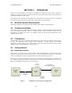
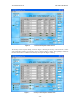
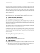
Factory users are allowed to control radio settings pertaining to output power level calibration. The
following figure depicts this expanded configuration.
13.6 VDC
Power
Supply
Primary
Power
Connector
STR-18xx
Radio
DB-25
Front Panel
Connector
Remote Front
Panel
Windows
Based
PC
Serial
Port
Serial
Port
SRI Assembly #
30-STR1800-01
Factory Programming Cable
DB-9
Front Panel
Connector
Figure 5 Factory Radio to PC Interconnect Configuration
For either mode, the 13.6 VDC power supply need only support the radio operation in a quiescent mode
(i.e., < 0.7 A).
3.4.2. Power-on Sequence
Once the above configuration has been established, the primary power supply and PC should be powered
on and initialized. The power up sequence of the radio versus the PC is not critical. However for the factory
configuration the 30-STR-1800-01 cable assembly must be connected to the radio prior to powering on the
radio. In this configuration the primary power will cause the remote front panel unit display to activate and
display configuration information. No such indication is available on the field configuration
3.4.3. Reading the Radio Configuration
Assuming the above process is successful, the user can proceed to activate the Radio Configuration
program.
There are two versions of the STR-1800 Control.exe Radio Configuration program with separate
functionality for Factory or Field use. Generally the Factory version has capabilities that are not available
to users of the Field version.
The Field version requires cabling as noted in Figure 4. Running the Field version of the application
provides a user interface screen as shown in Figure 6 below.