
Operations and Maintenance Manual


70-STR1800-00 Rev K STR-1800 O&M Manual
- 8 -
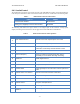
Pins not listed within this table are all defined as no connects.
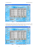
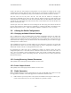
For the channel select lines described above, the following table defines the control functions of these
inputs.
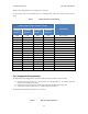
Table 6 Channel Selection Control Settings
FRONT PANEL 25 PIN D SIGNAL STATES
DEFINITION
CHANNEL
SELECT 3
CHANNEL
SELECT 2
CHANNEL
SELECT 1
CHANNEL
SELECT 0
High
High
High
High
Select Chan 1
High
High
High
Low
Select Chan 2
High
High
Low
High
Select Chan 3
High
High
Low
Low
Select Chan 4
High
Low
High
High
Select Chan 5
High
Low
High
Low
Select Chan 6
High
Low
Low
High
Select Chan 7
High
Low
Low
Low
Select Chan 8
Low
High
High
High
Select Chan 9
Low
High
High
Low
Select Chan 10
Low
High
Low
High
Select Chan 11
Low
High
Low
Low
Select Chan 12
Low
Low
High
High
Select Chan 13
Low
Low
High
Low
Select Chan 14
Low
Low
Low
High
Select Chan 15
Low
Low
Low
Low
Select Chan 16
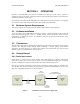
2.4.4 Diagnostic/Programming
The diagnostic/programming interface provides 3 different interfaces into the radio as follows:
1) RS-232 serial port interface for status/control and reprogramming of the modem processor
contained on the MDC of the design.
2) USB universal serial bus interface for the same purpose to the MDC modem processor.
3) A full duplex interface with power to a remote front panel for the unit.
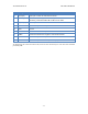
The pinouts associated with this connector are as follows:
Table 7 Reference Input Connectors