
Operations and Maintenance Manual


70-STR1800-00 Rev K STR-1800 O&M Manual
- 7 -
2.4.3 Audio/Control
The Audio/Control connector is located on the front of the STR-1800 series radios and is mounted directly
to the front panel mold of the radio. Characteristics of this connector are as indicated in the following table.
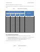
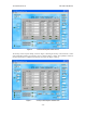
Table 4 Audio/Control Connector Characteristics
PINS (+/-)
SIGNAL
Connector Part Number
DB-25 Female
Mating (User Supplied) Connector Part Number
DB-25 Male
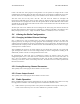
The following table defines the signal contents of all assigned pins on this connector. Analog inputs,
outputs, and analog channel select lines do not apply for the model STR-1821 or STR-1821A.
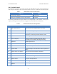
Table 5 Audio/Control Connector Pin Assignments
PIN
SIGNAL
DESCRIPTION AND CHARACTERISTICS
2
Audio Isolated Ground
Ground for the audio inputs/outputs of the radio
4
Receive Audio
Recovered audio signal output from the radio.
5
Channel Select 3
Control signal which when combined with Channel Select
0/1/2 forms a 4-bit binary channel selection control.
6
RS485 Out+
RS485 digital interface
7
Push-to-Talk (PTT)
Places the radio into transmit mode when low (i.e.,
grounded) or receive mode when high or floating.
8
RS485 Out-
RS485 digital interface
11
Audio Isolated Ground
Ground for the audio inputs/outputs of the radio
14
Channel Select 2
See pin 5 description above
17
Transmit Audio
Audio signal input to the radio when transmit operation is
active.
18
Channel Select Lines Ground
Ground for the Channel Select 0/1/2/3 lines
19
Channel Select 0
See pin 5 description above
21
PTT Isolated Ground
Ground for the PTT signal
23
Channel Select 1
See pin 5 description above
24
RS485 In+
RS485 digital interface
25
RS485 In-
RS485 digital interface