
Operations and Maintenance Manual

70-STR1800-00 Rev K STR-1800 O&M Manual
- 6 -
2.4 Connector Descriptions and Signal Definitions
This section describes the types of connectors used on the STR-1800 and provides the definition of the
signals associated with each.
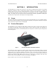
2.4.1 Primary Power
The Primary Power connector is located on the rear of the STR-1800 series radios and is attached to the
unit itself via approximately 6 inches of 14 gage wire. Characteristics of this connector are as indicated in
the following table.
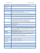
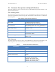
Table 2 Primary Power Connector Characteristics
PARAMETER
VALUES
Part number
Tyco/AMP Electronics P/N 172129-1
Female housing with male contact pins
Pin Assignments
When viewing contacts as a T, top horizontal pin is
+13.6 VDC while vertical descending pin is Ground
Input Voltage Range
13.6 VDC +/- 15%
Current Drain
9 Amps maximum
Connector to Radio Color Coding
13.6 VDC Contact – Red
Ground Contact - Black
Max. Fuse Rating (External)
STR-1820, STR-1820A, STR-1821A: 20 A
All Other: 10A
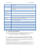
2.4.2 Antenna
The Antenna connector is located on the rear of the STR-1800 series radios and is mounted directly to the
main housing of the radio. Characteristics of this connector are as indicated in the following table.
Table 3 Antenna Port Connector Characteristics
PARAMETER
VALUES
Connector Type
UHF PL-259 Type Female
Antenna Impedance
50 Ohms
Maximum Output Power
45 Watts
Output Frequency Range
STR-1820, STR-1820A, STR-1821, STR-1821A:
400-470 MHz (FCC/IC/Cofetel)
STR-1830: 400-470 MHz (ETSI)
STR-1835: 450-512 MHz (Australia)
STR-1840: 136-174 MHz (ETSI)