
User Manual
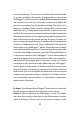
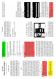
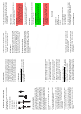

Table Of Contents

output August 19, 2019 8:28 Page 27
SulfiLogger™
Installation manual
Revision 1.00 (Valid from May 2019)
INTRODUCTION
This guide covers the steps required to in-
stall the SulfiLogger
™
sensor, including the
electrical and mechanical installation pro-
cedures. For further information about the
use and maintenance of the product, we
kindly refer to the latest User Manual avail-
able at
www.SulfiLogger.com
. Warranty
and legal information are described in the
terms and conditions of your order confir-
mation and also available upon request.
SAFETY
Please read this manual carefully before un-
packing, installing or operating the device.
Although the operation of the SulfiLogger
™
sensor is straightforward, it is mandatory to
be familiar with the content of this manual.
Failure to do so may result in serious injury
to operators or other persons, or damage
to equipment. Do not use or install the Sul-
fiLogger
™
sensor and auxiliary equipment
in any other way than specified in this man-
ual. Special attention must be paid to all
danger and caution statements. Do not use
the SulfiLogger
™
sensor outside the speci-
fied electrical, mechanical and thermal pa-
rameters as specified in the data sheet. Dur-
ing the installation, please wear personal
protective equipment (PPE) according to
the safety regulation of the installation site.
Hazard statement nomenclature
DANGER
Indicates a potentially or imminently
hazardous situation which, if not
avoided, could result in death or seri-
ous injury.
!
CAUTION
Indicates a potentially hazardous situ-
ation that may result in minor or mod-
erate injury.
IMPORTANT NOTE
Information that requires special em-
phasis.
Hazardous areas - SulfiLogger™ sensor
EX version
•
Pay close attention to other EX equip-
ment used in conjunction with the Sul-
fiLogger™ sensor.
•
Observe the specifications in the certifi-
cate as well as national and local regula-
tions.
•
Ensure that all personnel are suitably
qualified.
•
Always use approved EX barriers for in-
stallation.
Chemical and gas handling safety
DANGER
Handling hazardous gases such as hy-
drogen sulfide or chemical samples
containing dissolved sulfides can be
dangerous. Users of this product are
advised to familiarize themselves with
safety procedures, use of personal pro-
tective equipment (PPE) and the cor-
rect use of gases and/or chemicals, and
to carefully read all relevant Safety
Data Sheets.
Installation and calibration of the SulfiLog-
ger
™
sensor may include the risk of con-
tact with hazardous gases or liquids. Hydro-
gen sulfide is a highly toxic gas and special
precautions are needed to avoid the risk of
injury or death. Furthermore, the installa-
tion of the SulfiLogger
™
sensor in applica-
tions such as sewer networks or other facil-
ities containing raw wastewater includes a
risk of contact with a range of other chem-
ical and biological threats, and any opera-
tor performing installation or service on the
SulfiLogger
™
sensor in such environments
should therefore be trained in the environ-
mental safety and need of PPE for the given
application. This manual does not cover any
such training. The use of the SulfiLogger
™
sensor for specific applications may involve
risks that are not mentioned here.
OVERVIEW
The SulfiLogger
™
sensor is available in dif-
ferent configurations in an ATEX certified
version (X1 sensors) and a non-ATEX certi-
fied version (S1 sensors). If your product
is an ATEX certified product, it is crucial
that you carefully follow the instructions re-
lating to ATEX specific installation require-
ments.
EU - ATEX certification
The SulfiLogger™ X1 sensor has the follow-
ing marking:
ELECTRICAL INSTALLATION
Barriers for SulfiLogger™ X1 installation
When using the SulfiLogger
™
sensor, a
Zener barrier or EX isolator MUST always
be used. We recommend using barriers
tested and approved by Unisense.
Hazardous area Safe area
Apparatus,
e.g. SCADA
Zener barrier
4-20 mA / power
EX isolator
or
RS-232
Zener barrier
EX isolator
or
Connection
The SulfiLogger
™
sensor has two connec-
tors: A 4-20 mA power connector (5-pin
M12 male) and an RS-232 connector (5-pin
M12 female). We recommend using M12
plugs in stainless steel (EN 1.4404 / 316L).
These cables can be provided by Unisense.
Please note that products powered by a
battery box may require special attention.
Please refer to the latest User Manual.
Port parameters
Please note that the colors listed here only
apply for cables supplied by Unisense. The
SulfiLogger
™
is designed for 4-20 mA loop-
power. However, this connector can also be
used only for DC supply.
Power / 4-20 mA
Pin Color Connection
1 Brown Positive (+12 to 24 v)
2 White Not connected
3 Blue Negative (-)
4 Black Not connected
5 Gray Not connected
Communication (RS-232)
Pin Color Connection
1 Brown TXD
2 White Not connected
3 Blue RXD
4 Black GND
5 Gray Not connected
Grounding
The SulfiLogger
™
sensor should always be
grounded. However, national, regional or
local regulation may apply. For use in
ATEX-regulated areas, see EN/IEC 60079-
14. Unisense recommends that the SulfiLog-
ger
™
sensor is always grounded using the
M6 thread at the back of the device for a
secure grounding connection.
DANGER
Using a SulfiLogger
™
sensor from the
X1-series without grounding will void
the ATEX certificate.