
Data Sheet

%
4. Peripheral Interface
4.10. LED Light and Button
ESP8266EX features 17 GPIOs, all of which can be assigned to support various functions
of LED lights and buttons. Definitions of some GPIOs that are assigned with certain
functions in demo application design are shown as below.
Altogether three interfaces have been defined, one is for the button, while the other two are
for LED light. Generally, MTCK is used for controlling the reset button; GPIO0 is used as an
signal to indicate the Wi-Fi working state; MTDI is used as a signal light to indicate
communication status between the device and the server.
RF Calibration Process
Optimize the RF circuit conditions based on the value of vdd33_const. The
permissible error is ±0.2V.
User Programming
Use system_adc_readinstead of system_get_vdd33.
📖 Notes:
esp_init_data_default.bin is provided in SDK package which contains RF initialization parameters (0 ~
127 bytes).
You can define the 107th byte in esp_init_data_default.bin to vdd33_const as below.
• If vdd33_const = 0xff, the power voltage of Pin 3 and Pin 4 will be tested by the internal self-
calibration process of ESP8266EX itself. RF circuit conditions should be optimized according to
the testing results.
• If 18 =< vdd33_const =< 36, ESP8266EX RF Calibration and optimization process is implemented
via (vdd33_const/10).
• If vdd33_const < 18 or 36 < vdd33_const < 255, ESP8266EX RF Calibration and optimization
process is implemented via the default value 2.5V.
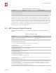
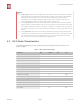
Table 4-10. Pin Definition of LED and Button
Pin Name
Pin Num
IO
Function Name
MTCK
12
IO 13
Button (Reset)
GPIO0
15
IO 0
Wi-Fi Light
MTDI
10
IO 12
Link Light
📖 Note:
Most interfaces described in this chapter can be multiplexed. Pin definitions that can be defined is not
limited to the ones herein mentioned; you can customize the functions of the pins according to your
specific application scenarios via software programming and hardware design.
Espressif
% /%18 25
2017.04