
Data Sheet

%
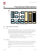
4. Peripheral Interface
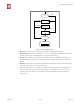
Data transfers to/from UART interfaces can be implemented via hardware. The data
transmission speed via UART interfaces reaches 115200 x 40 (4.5 Mbps).
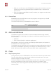
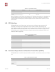
UART0 can be used for communication. It supports fluid control. Since UART1 features
only data transmit signal (Tx), it is usually used for printing log.
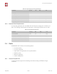
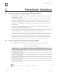
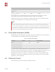
4.7. Pulse-Width Modulation (PWM)
ESP8266EX has four PWM output interfaces. They can be extended by users themselves.
The pin definitions of the PWM interfaces are defined as below.
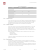
The functionality of PWM interfaces can be implemented via software programming. For
example, in the LED smart light demo, the function of PWM is realized by interruption of the
timer, the minimum resolution reaches as high as 44 ns. PWM frequency range is
adjustable from 1000 μs to 10000 μs, i.e., between 100 Hz and 1 kHz. When the PWM
frequency is 1 kHz, the duty ratio will be 1/22727, and a resolution of over 14 bits will be
achieved at 1 kHz refresh rate.
4.8. IR Remote Control
One Infrared remote control interface is defined as below.
MTCK
12
IO13
U0CTS
UART1
GPIO2
14
IO2
U1TXD
SD_D1
23
IO8
U1RXD
Pin Type
Pin Name
Pin Num
IO
Function Name
📖 Note:
By default, UART0 outputs some printed information when the device is powered on and booting up. The
baud rate of the printed information is relevant to the frequency of the external crystal oscillator. If the
frequency of the crystal oscillator is 40 MHz, then the baud rate for printing is 115200; if the frequency of
the crystal oscillator is 26 MHz, then the baud rate for printing is 74880. If the printed information exerts
any influence on the functionality of the device, it is suggested to block the printing during the power-on
period by changing (U0TXD, U0RXD) to (MTDO, MTCK).
Table 4-7. Pin Definitions of PWM
Pin Name
Pin Num
IO
Function Name
MTDI
10
IO12
PWM0
MTDO
13
IO15
PWM1
MTMS
9
IO14
PWM2
GPIO4
16
IO4
PWM3
Espressif
% /%16 25
2017.04