
Data Sheet

%
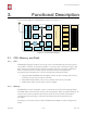
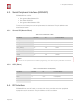
4. Peripheral Interface
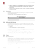
Both I2C Master and I2C Slave are supported. I2C interface functionality can be realized via
software programming, and the clock frequency is 100 kHz at a maximum. It should be
noted that I2C clock frequency should be higher than the slowest clock frequency of the
slave device.
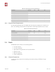
4.5. I2S Interface
ESP8266EX has one I2S data input interface and one I2S data output interface. I2S
interfaces are mainly used in applications such as data collection, processing, and
transmission of audio data, as well as the input and output of serial data. For example, LED
lights (WS2812 series) are supported. The pin definition of I2S is shown in Table 4-5. I2S
functionality can be enabled via software programming by using multiplexed GPIOs, and
linked list DMA is supported.
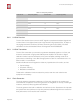
4.6. Universal Asynchronous Receiver Transmitter (UART)
ESP8266EX has two UART interfaces UART0 and UART, the definitions are shown in Table
4-6.
Table 4-4. Pin Definitions of I2C
Pin Name
Pin Num
IO
Function Name
MTMS
9
IO14
I2C_SCL
GPIO2
14
IO2
I2C_SDA
Table 4-5. Pin Definitions of I2S
I2S Data Input
Pin Name
Pin Num
IO
Function Name
MTDI
10
IO12
I2SI_DATA
MTCK
12
IO13
I2SI_BCK
MTMS
9
IO14
I2SI_WS
MTDO
13
IO15
I2SO_BCK
U0RXD
25
IO3
I2SO_DATA
GPIO2
14
IO2
I2SO_WS
Table 4-6. Pin Definitions of UART
Pin Type
Pin Name
Pin Num
IO
Function Name
UART0
U0RXD
25
IO3
U0RXD
U0TXD
26
IO1
U0TXD
MTDO
13
IO15
U0RTS
Espressif
% /%15 25
2017.04