
Data Sheet
%
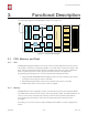
4. Peripheral Interface
4. Peripheral Interface
4.1. General Purpose Input/Output Interface (GPIO)
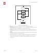
ESP8266EX has 17 GPIO pins which can be assigned to various functions by programming
the appropriate registers.
Each GPIO can be configured with internal pull-up or pull-down, or set to high impedance,
and when configured as an input, the data are stored in software registers; the input can
also be set to edge-trigger or level trigger CPU interrupts. In short, the IO pads are bi-
directional, non-inverting and tristate, which includes input and output buffer with tristate
control inputs.
These pins can be multiplexed with other functions such as I2C, I2S, UART, PWM, IR
Remote Control, LED Light and Button etc.
For low power operations, the GPIOs can also be set to hold their state. For instance, when
the chip is powered down, all output enable signals can be set to hold low.
Optional hold functionality can be built into the IO if requested. When the IO is not driven by
the internal or external circuitry, the hold functionality can be used to hold the state to the
last used state. The hold functionality introduces some positive feedback into the pad.
Hence, the external driver that drives the pad must be stronger than the positive feedback.
The required drive strength is small — in the range of 5 μA to pull apart the latch.
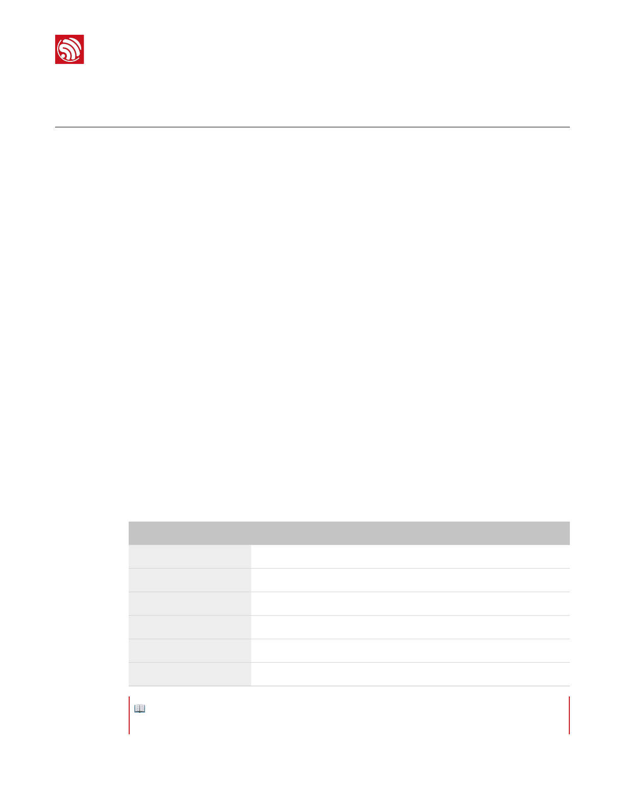
4.2. Secure Digital Input/Output Interface (SDIO)
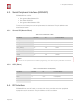
ESP8266EX has one Slave SDIO, the definitions of which are described as Table 4-1.
Table 4-1. Pin Definitions of SDIOs
Pin Name
Pin Num
IO
Function Name
SDIO_CLK
21
IO6
SDIO_CLK
SDIO_DATA0
22
IO7
SDIO_DATA0
SDIO_DATA1
23
IO8
SDIO_DATA1
SDIO_DATA_2
18
IO9
SDIO_DATA_2
SDIO_DATA_3
19
IO10
SDIO_DATA_3
SDIO_CMD
20
IO11
SDIO_CMD
📖 Note:
4-bit 25 MHz SDIO v1.1 and 4-bit 50 MHz SDIO v2.0 are supported.
Espressif
% /%13 25
2017.04