
Data Sheet

%
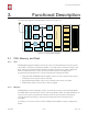
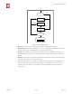
3. Functional Description
3.4.2. 2.4 GHz Receiver
The 2.4 GHz receiver down-converts the RF signals to quadrature baseband signals and
converts them to the digital domain with 2 high resolution high speed ADCs. To adapt to
varying signal channel conditions, RF filters, automatic gain control (AGC), DC offset
cancelation circuits and baseband filters are integrated within ESP8266EX.
3.4.3. 2.4 GHz Transmitter
The 2.4 GHz transmitter up-converts the quadrature baseband signals to 2.4 GHz, and
drives the antenna with a high-power CMOS power amplifier. The function of digital
calibration further improves the linearity of the power amplifier, enabling a state of art
performance of delivering +19.5 dBm average power for 802.11b transmission and +16
dBm for 802.11n transmission.
Additional calibrations are integrated to offset any imperfections of the radio, such as:
• Carrier leakage
• I/Q phase matching
•
Baseband nonlinearities
These built-in calibration functions reduce the product test time and make the test
equipment unnecessary.
3.4.4. Clock Generator
The clock generator generates quadrature 2.4 GHz clock signals for the receiver and
transmitter. All components of the clock generator are integrated on the chip, including all
inductors, varactors, filters, regulators and dividers.
The clock generator has built-in calibration and self test circuits. Quadrature clock phases
and phase noise are optimized on-chip with patented calibration algorithms to ensure the
best performance of the receiver and transmitter.
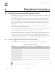
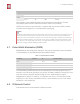
Table 3-4. Frequency Channel
Channel No.
Frequency (MHz)
Channel No.
Frequency (MHz)
1
2412
8
2447
2
2417
9
2452
3
2422
10
2457
4
2427
11
2462
5
2432
12
2467
6
2437
13
2472
7
2442
14
2484
Espressif
% /%10 25
2017.04