
Product Manual


www.ssilocators.com
13
SERIES
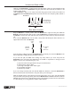
Move to the location you want to measure depth. Stay at least 15 feet away from the transmItter.
Move the
receIver left to right across the path until the cable is located.
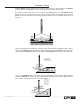
1. Mark the path on the ground as precisely as possible using the Null method.
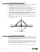
2. Place the receIver on the ground with the LCD meter facing up. Position the unit so that the sight
lines on the lower tube are straight up and down orienting the unit at a 45º angle.
3. Pull the
receIver away from the cable path (at 90º to the cable path) keeping the unit at 45º.
4. When the
receIver indicates a Null reading, mark the location of the receIver's foot.
5. The distance between the receIver and the cable path is the depth of the pipe or cable. A false
depth reading may be caused by nearby buried metallic objects, such as a second cable, pipe,
sewer, fence or railroad track or from the signal conducting on multiple lines.
6. Conrm the depth measurement by repeating the above steps on the opposite side of the pipe or
cable.
7. A variance greater than 5 inches in depth measurement may indicate interference from adjacent
cables, pipes or other objects.
Buried cable or pipe (End view)
GroundGround
Signal Null Point Signal Null Point
Depth
Depth
45°
45°
depth measurement 45º angle method
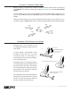
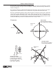
When adjacent cables or pipes are present, they will sometimes create locating errors. Some of the
transmItter signal is picked up by the adjacent conductors and is redirected so that it combines
with the original signal. The result is a Tilted Magnetic Field. This is often the reason that numeric
depth readouts are sometimes created in error.
The operator can verify the accuracy of path locate by performing the 45º Angle Method locate on
both sides of the cable path. If the right and left side depth readings agree to within 5 inches, the
path locate is accurate. If the two depth readings do not agree, then dig with care. A closer locate
would be halfway between the two outside depth locate marks.
This is an important technique that should be used to ensure the most accurate location possible.
tilted magnetiC field identifiCation