
Product Manual


3-2
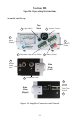
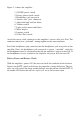
Figure 3-1 shows the amplifier:
1. ON/OFF power switch
2. Battery power check switch
3. Headphones jack receptacle
4. Sensor cable “jack” connector
5. Adjustable high and low filters
6. Volume control
7. Light switch (meter and filters)
8. Meter display
9. Limitter switch
10. Filter-Thru switch
Attach the sensor cable connector to the amplifier’s sensor cable jack. Note: The
connector and jack are “polarized”, mating together in only one orientation.
Install the headphones plug connector into the headphones jack receptacle on the
amplifier. Note: the headphones jack receptacle is power “switched”, such that
the headphones must be attached in order for the amplifier's power to turn ON. If
the headphones are not attached to the amplifier, the power will not turn ON.
Battery Power and Battery Check
With the amplifier’s power ON, the user can check the condition of the batteries.
Depress the BATT switch and observe the amplifier’s meter deflection. The bat-
teries are still good if the meter needle deflects into the red line labeled BATT. If
the needle falls below the red line, replace all six of the batteries soon.