Table of Contents Section Section I. Sensor Damage and Personal Safety Precautions 1-1 Section II. Components, Standard Accessories & Optional Accessories 2-1 Section III.
List of Figures Figure 3-1 3-2 3-3 3-4 3-5 3-6 Title Amplifier Connectors & Controls LD-12 with Ground Microphone Listening Ranges for Combinations of Filters Limitter and Filter-Thru Switches Ground Microphone for Streets Magnet Base for Hydrants & Valves 4-1 Sound Intensity vs. Water Pressure Graph 4-2 Filtered Frequencies Graphs 4-3 Absorption of Sound Frequencies by Soil 4-4 Sound Attenuation of Different Frequencies by 4 feet of Soil 4-5 Sound Transmission vs.
Section I Sensor Damage and Personal Safety Precautions Warning! The LD-12 can damage human hearing if it is used improperly. Always follow these procedures for safe use: 1. Turn the amplifier volume down to twenty-five percent (25%) or less before putting on the headphones. 2. Position the ground microphone (or sensor with magnet base) firmly on the street or other listening surface before depressing the mute switch. 3.
Section II Components, Standard Accessories & Optional Accessories The LD-12 consists of the following component items and standard accessories: 1. Ground microphone and handswitch (mute) with three (3) pronged base and forty (40) inch long sensor cable 2. Amplifier with power switch, volume control, meter display of sound intensity (and battery power), adjustable low and high frequency filters, Limitter switch, Filter-Thru switch, and Lights switch. 3. Stereo headphones 4. Magnet base accessory 5.
Section III.
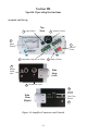
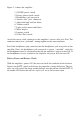
Figure 3-1 shows the amplifier: 1. ON/OFF power switch 2. Battery power check switch 3. Headphones jack receptacle 4. Sensor cable “jack” connector 5. Adjustable high and low filters 6. Volume control 7. Light switch (meter and filters) 8. Meter display 9. Limitter switch 10. Filter-Thru switch Attach the sensor cable connector to the amplifier’s sensor cable jack. Note: The connector and jack are “polarized”, mating together in only one orientation.
Figure 3-2 LD-12 with Ground Microphone Hand Switch and Mute Button Figure 3-2 shows the completely assembled LD-12 with the ground microphone positioned firmly on the street's surface directly over the water line. The mute button in the handswitch shown in the user's hand is depressed only when the ground microphone and cables are completely stationary and the user is ready to hear the leak. Sound will not be heard until the mute switch button is depressed.
location (on the street, at the meters, etc.) is louder. Often the meter can distinguish which location is louder when the user’s hearing can not tell. High and Low Frequency Filters Figure 3-1 shows the three (3) low frequency filter switches and the three (3) high frequency filter switches. The three (3) low frequency filters are set at 100 Hz, 200 Hz and 400 Hz. If the 100 Hz filter switch is depressed, then all noises and sounds at 100 Hz frequency and lower are filtered out.
LIGHT Switch for Meter and Filters Figure 3-1 shows the LIGHT switch located on the amplifier’s face between the volume control knob and the meter. The LIGHT switch allows the user to turn ON or OFF the meter backlight and the light switches for the filters. If the LIGHT switch is turned OFF, the meter and the filter switches operate normally, but their power consumptions are greatly reduced. By operating the amplifier with the LIGHT switch turned OFF, the battery lives are doubled.
Figure 3-4 Limitter and Filter-Thru Switches Filter-Thru Switch (Amplifier Right Side) Figure 3-4 shows a side view of the amplifier with the Filter-Thru switch in the OFF position. When the Filter-Thru switch is turned ON, the filter switches on the face of the amplifier are completely by-passed, and there is no filtering of sounds at all. The user hears all sounds from 50 Hz to 15,000 Hz (or to the extent of his or her hearing).
Figure 3-5 Ground Microphone for Streets Ground Microphone Base for Streets Figure 3-5 shows a side view of the ground microphone with the three (3) pronged base for listening on streets, pavement surfaces, or concrete slabs. The 3 prongs should rest firmly on the street's hard surface in order for sound to be transmitted clearly to the ground microphone's sensor.
Contact Rod for Soil and Brass Valves The contact rod is provided to assist in contacting the sensor to materials that are soft, spongy, porous, or non-ferrous. To use, remove the nut on the base of the ground microphone with the nutdriver and attach the contact rod to the brass thread. If only a short rod is needed, attach only the pointed section of the contact rod to the bottom of the sensor.
Section IV General Strategies for Water Leak Detection Types of Water Leak Sounds There are three different, commonly identified sounds produced by water leaks: 1. Pipe resonance and vibration from orifice pressure reduction. 2. Water impaction on the surrounding soil. 3. Water circulation and flow in the surrounding soil cavity. Resonance or pipe vibration is often the loudest or most intense leak noise, sounding like a "whoosh" or a "hiss.
Sound Intensity (Amplitude) 15 30 45 60 75 Water Pressure (psi) Figure 4-1 Sound Intensity vs. Water Pressure Graph Metal pipes, such as iron mains, copper services, and steel pipes, transmit water leak sounds that are louder and higher in frequency than do PVC pipes or asbestos-cement pipes. Thus, knowledge of the pipe material is important (see Figure 4-2).
Large diameter pipes, whether they are PVC, concrete, steel, or iron, transmit much less sound from water leaks and produce lower frequency sounds than small diameter pipes. Because of their mechanical properties, large diameter iron and steel pipes, such as 24 inches diameter and greater, resonate with much lower frequency leak sounds than the smaller diameter iron and steel pipes, such as 6 inches and 8 inches.
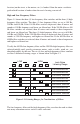
-20 Sound Attenuation (dB) -40 -60 -80 200 1,000 5,000 Frequency (Hz) Figure 4-4 Sound Attenuation of Different Frequencies by 4 feet of Soil Finally, the ground cover, whether it is an asphalt street, loose dirt, concrete slab, or grass lawn, also makes an important difference. Hard street surfaces and concrete slabs resonate with the sounds of the water leak, and the leak may be heard for 5 to 10 feet or more on either side of the water pipe.
Distances transmitted for the sounds of water leaks are a function of the pipe diameter as well as the pipe material (see table below). Pipe Material and Diameter Typical Max.
Figure 4-6 Leak Survey at a Hydrant As previously discussed, knowledge of the pipe material and pipe diameter is important in order to know whether a thorough survey can be performed only by listening at hydrants and valves that are 500 to 600 feet apart. During the water leak survey, if the sounds of a possible water leak are heard at a hydrant or valve, the LD-12 user then checks at every immediate, nearby lateral valve, hydrant valve, and residential or commercial service line.
Maximum leak noises Rapid attenuation of noises Water Leak Figure 4-7 Water Leak Pinpointing To find this spot, the LD-12 user must carefully mark the location of the water line on the street after locating it exactly with a pipe and cable locator. Usually, the piping between the valve or hydrant with the loudest sound and the valve or hydrant with the second loudest sound is the section of the line that needs to be marked.
Figure 4-8 Leak Survey at a Meter Filtering Out Extraneous Noises Often there are extraneous noises at a water leak job site, like traffic, wind, AC hum, etc., that can make leak detection difficult, particularly water leak pinpointing on the street. The 200 Hz filter or the 400 Hz filter may be effective at reducing the interference from these extraneous noises.
Figure 4-9 Leak Pinpointing Over a Hydrant Line 4-9
Section V Specifications Amplifier • Input Impedance : 50k ohms • Output Impedance : 15 ohms • Amplification : 62 dB +/- 3dB • Frequency Range : 1) 100Hz to 1200Hz (13 dB) with Filter-Thru OFF 2) 15Hz to 30,000Hz (13 dB) with Filter-Thru ON • Power : 6 AA dry cell batteries • Power Consumption : 1) 70 mA or less with backlight ON 2) 35 mA or less with backlight OFF • Battery Life : 1) 28 hours with backlight OFF (alkaline cells) 2) 14 hours with backlight ON (alkaline
Section VI Warranty Statement SubSurface Leak Detection, Inc. (SubSurface) warrants each product of its manufacture to be free from defects in material and workmanship subject to the following terms and conditions. The warranty is effective for sixty months after shipment by SubSurface to the original purchaser. Our obligation under the warranty is limited to servicing or adjusting any product returned to the factory for this purpose and to replace any defective part thereof.