E SERIES BUILT-IN OVENS INSTALLATION INSTRUCTIONS INSTRUCCIONES DE INSTALACIÓN INSTRUCTIONS D’INSTALLATION ISTRUZIONI PER L’INSTALLAZIONE INSTALLATIONSANWEISUNGEN
ENGLISH 4 ESPÃNOL 22 FRANÇAIS 40 I TA L I A N O 58 DEUTSCH 76 3
C O N TA C T I N F O R M AT I O N Website: wolfappliance.com As you follow these instructions, you will notice WARNING and CAUTION symbols. This blocked information is important for the safe and efficient installation of Wolf equipment. There are two types of potential hazards that may occur during installation. signals a situation where minor injury or product damage may occur if you do not follow instructions. states a hazard that may cause serious injury or death if precautions are not followed.
W O L F E S E R I E S B U I LT- I N OV E N S I N S TA L L AT I O N R E Q U I R E M E N T S S I T E P R E PA R AT I O N IMPORTANT NOTE: This installation must be completed by a qualified technician. IMPORTANT NOTE: A minimum 610 mm of usable cabinet depth is required, or the back panel of the cabinet may need to be removed for proper installation. A minimum 635 mm of usable cabinet depth is required for a flush inset installation. The electrical box must be flush with the back panel of the cabinet.
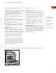
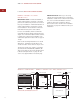
W O L F E S E R I E S B U I LT- I N OV E N S E S E R I E S B U I LT- I N S I N G L E OV E N S MODELS ICBSO30-2F/S AND ICBSO30-2U/S IMPORTANT NOTE: A minimum 610 mm of usable cabinet depth is required, or the back panel of the cabinet may need to be removed for proper installation. A minimum 635 mm of usable cabinet depth is required for a flush inset installation. The electrical box must be flush with the back panel of the cabinet.
I N S TA L L AT I O N I N S T R U C T I O N S E S E R I E S B U I LT- I N S I N G L E OV E N S S TA N D A R D I N S TA L L A T I O N C O M B I N A T I O N I N S TA L L A T I O N S IMPORTANT NOTE: For standard installations, a minimum 610 mm of usable cabinet depth is required, or the back panel of the cabinet may need to be removed for proper installation. The electrical box must be flush with the back panel of the cabinet.
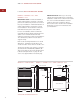
W O L F E S E R I E S B U I LT- I N OV E N S E S E R I E S B U I LT- I N S I N G L E OV E N S S TA N D A R D I N S TA L L A T I O N Overall Oven Width 759 mm Minimum Cabinet Width 762 mm Overall Oven Height 708 mm Minimum Cabinet (Opening) Depth 610 mm Overall Oven Depth (behind frame) 603 mm Opening Width 724 mm Open Door Clearance 559 mm Opening Height 691 mm Recommended Cabinet Width 838 mm Minimum Base Support 113 kg S TA N D A R D I N S TA L L A T I O N – M O D E L S I C B S O 3 0
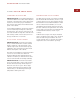
I N S TA L L AT I O N I N S T R U C T I O N S E S E R I E S B U I LT- I N S I N G L E OV E N S F L U S H I N S E T I N S TA L L A T I O N Overall Oven Width 759 mm Minimum Cabinet Width 838 mm Overall Oven Height 708 mm Minimum Flush Inset Depth 635 mm Overall Oven Depth (behind frame) 603 mm Opening Width 724 mm Open Door Clearance 559 mm Minimum Flush Inset Width 772 mm Opening Height 691 mm Minimum Flush Inset Height 724 mm Minimum Base Support 113 kg F L U S H I N S E T I N S TA
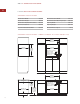
W O L F E S E R I E S B U I LT- I N OV E N S E S E R I E S B U I LT- I N D O U B L E OV E N S MODELS ICBDO30-2F/S AND ICBDO30-2U/S IMPORTANT NOTE: A minimum 610 mm of usable cabinet depth is required, or the back panel of the cabinet may need to be removed for proper installation. A minimum 635 mm of usable cabinet depth is required for a flush inset installation. The electrical box must be flush with the back panel of the cabinet.
I N S TA L L AT I O N I N S T R U C T I O N S E S E R I E S B U I LT- I N D O U B L E OV E N S S TA N D A R D I N S TA L L A T I O N F L U S H I N S E T I N S TA L L A T I O N IMPORTANT NOTE: For standard installations, a minimum 610 mm of usable cabinet depth is required, or the back panel of the cabinet may need to be removed for proper installation. The electrical box must be flush with the back panel of the cabinet.
W O L F E S E R I E S B U I LT- I N OV E N S E S E R I E S B U I LT- I N D O U B L E OV E N S S TA N D A R D I N S TA L L A T I O N Overall Oven Width 759 mm Overall Oven Height 1292 mm Minimum Cabinet Width 762 mm Minimum Cabinet (Opening) Depth 610 mm Overall Oven Depth (behind frame) 603 mm Opening Width 724 mm Open Door Clearance 559 mm Opening Height 1260 mm Recommended Cabinet Width 838 mm Minimum Base Support 181 kg S TA N D A R D I N S TA L L A T I O N – M O D E L S I C B D O 3
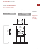
I N S TA L L AT I O N I N S T R U C T I O N S E S E R I E S B U I LT- I N D O U B L E OV E N S F L U S H I N S E T I N S TA L L A T I O N Overall Oven Width 759 mm Overall Oven Height 1292 mm Minimum Cabinet Width 838 mm Minimum Flush Inset Depth 635 mm Overall Oven Depth (behind frame) 603 mm Opening Width 724 mm Open Door Clearance 559 mm Minimum Flush Inset Width 772 mm Minimum Base Support 181 kg Opening Height 1260 mm Minimum Flush Inset Height 1294 mm F L U S H I N S E T I N S
W O L F E S E R I E S B U I LT- I N OV E N S S TA N DA R D I N S TA L L AT I O N O P T I O N S E S E R I E S B U I L T- I N S I N G L E O V E N The Wolf E Series single oven may be installed in combination with a Wolf convection or nonconvection microwave oven with 762 mm E Series trim kit, and a Wolf warming drawer with E Series stainless steel drawer front or integrated drawer front. Refer to the illustration below, and pages 6–9 for installation specifications for E Series single ovens.
I N S TA L L AT I O N I N S T R U C T I O N S S TA N DA R D I N S TA L L AT I O N O P T I O N S E S E R I E S B U I L T- I N D O U B L E O V E N The Wolf E Series double oven may be installed in combination with a Wolf warming drawer with E Series stainless steel drawer front or integrated drawer front. Refer to the illustration below, and pages 10–13 for installation specifications for E Series double ovens.
W O L F E S E R I E S B U I LT- I N OV E N S ELECTRICAL R E Q U I R E M E N T S Verify that power is disconnected from the electrical box before proceeding. I M P O R TA N T N OT E Be aware of local codes and ordinances when installing your service. E SERIES SINGLE OVENS Required power supply: 220-240V AC, 50/60 Hz Maximum connected load: 5.
I N S TA L L AT I O N I N S T R U C T I O N S ELECTRICAL R E Q U I R E M E N T S I N S TA L L I N G T H E O V E N With the oven positioned directly in front of the cabinet opening, feed the properly rated cord attached to the oven terminal box through the opening in the cabinet platform (where applicable). Then, depending upon local codes, utilize one of the following techniques to connect the appliance to the electrical power supply. U N PA C K T H E O V E N Oven is not mounted to the shipping base.
W O L F E S E R I E S B U I LT- I N OV E N S I N S TA L L I N G T H E O V E N O V E N D O O R R E M O VA L To reduce the weight of the oven and ease installation, removal of the oven door(s) is an option. To Remove Oven Door: POSITION THE OVEN The oven is very heavy—use caution when lifting. It is recommended that two people lift and position the oven into the opening. Wear gloves to protect hands from any sharp edges. Open oven door all the way. Flip down the hinge latch on each side.
I N S TA L L AT I O N I N S T R U C T I O N S I N S TA L L I N G T H E O V E N M O U N T O V E N T O C A B I N E T RY O V E N O P E R AT I O N Once the oven is fully inserted into the cabinet opening, locate the mounting holes on the oven side trim. There will be four mounting holes for a single oven and six for a double oven. Refer to the illustration below. Use a 2 mm drill bit to drill pilot holes into the cabinet.
W O L F E S E R I E S B U I LT- I N OV E N S TROUBLES H O OT I N G IMPORTANT NOTE: If the built-in oven does not operate properly, follow these troubleshooting steps: C O N TA C T I N F O R M AT I O N Website: wolfappliance.com Verify that power is being supplied to the oven. Check the electrical connections to ensure that the installation has been completed correctly. Follow troubleshooting procedures as described in the Wolf E Series Built-In Ovens Use & Care Information.
The information and images in this book are the copyright property of Wolf Appliance, Inc., an affiliate of Sub-Zero, Inc. Neither this book nor any information or images contained herein may be copied or used in whole or in part without the express written permission of Wolf Appliance, Inc., an affiliate of Sub-Zero, Inc. ©Wolf Appliance, Inc. all rights reserved.
INFORMACIÓN D E C O N TA C T O Página Web: www.sub-zero.eu.com Cuando consulte las instrucciones que aparecen en esta guía, encontrará símbolos de AVISO y PRECAUCIÓN. Esta información en recuadros es importante para instalar el equipo de Wolf de forma segura y eficaz. Existen dos tipos de posibles riesgos que pueden producirse durante una instalación. PRECAUCIÓN indica una situación en la que se pueden sufrir heridas leves o provocar daños secundarios al producto si no se siguen las instrucciones.
H O R N O S I N T E G R A B L E S S E R I E E D E WO L F R E Q U I S I T O S D E I N S TA L AC I Ó N P R E PA R A C I Ó N D E L SITIO NOTA IMPORTANTE: Esta instalación debe ser realizada por un técnico cualificado. NOTA IMPORTANTE: Es necesario dejar un fondo mínimo de 610 mm utilizables, si no, podría ser necesario quitar el panel trasero del armario para que el horno quede bien instalado. En el caso de una instalación empotrable, es necesario dejar un fondo mínimo de 635 mm utilizables.
H O R N O S I N T E G R A B L E S S E R I E E D E WO L F HORNOS SENCILLOS INTEGRABLES SERIE E MODELOS ICBSO30-2F/S Y ICBSO30-2U/S NOTA IMPORTANTE: Es necesario dejar un fondo mínimo de 610 mm utilizables, si no, podría ser necesario quitar el panel trasero del armario para que el horno quede bien instalado. En el caso de una instalación empotrable, es necesario dejar un fondo mínimo de 635 mm utilizables. La caja de conexiones debe empotrarse con el panel trasero del armario.
I N S T R U C C I O N E S D E I N S TA L AC I Ó N HORNOS SENCILLOS INTEGRABLES SERIE E I N S TA L A C I Ó N E S T Á N D A R I N S TA L A C I O N E S C O M B I N A D A S NOTA IMPORTANTE: Para las instalaciones estándar, es necesario dejar un fondo mínimo de 610 mm utilizables, si no, podría ser necesario quitar el panel trasero del armario para que el aparato quede bien instalado. La caja de conexiones debe empotrarse con el panel trasero del armario.
H O R N O S I N T E G R A B L E S S E R I E E D E WO L F HORNOS SENCILLOS INTEGRABLES SERIE E I N S TA L A C I Ó N E S T Á N D A R Anchura total del horno 759 mm Anchura mínima del mueble 762 mm Altura total del horno 708 mm Fondo mínimo del armario (apertura) 610 mm Fondo total del horno (marco posterior) 603 mm Anchura de la cavidad 724 mm Margen de apertura de la puerta 559 mm Altura de la cavidad 691 mm Anchura del armario recomendada 838 mm Soporte mínimo de la base I N S TA L A C I
I N S T R U C C I O N E S D E I N S TA L AC I Ó N HORNOS SENCILLOS INTEGRABLES SERIE E I N S TA L A C I Ó N E M P O T R A B L E Anchura total del horno 759 mm Altura total del horno 708 mm Fondo total del horno (marco posterior) 603 mm Margen de apertura de la puerta Soporte mínimo de la base 559 mm 113 kg Anchura mínima del mueble 838 mm Fondo mínimo de instalación empotrable 635 mm Anchura de la cavidad 724 mm Anchura mínima de instalación empotrable 772 mm Altura de la cavidad 691 mm Al
H O R N O S I N T E G R A B L E S S E R I E E D E WO L F HORNOS DOBLES INTEGRABLES SERIE E MODELOS ICBDO30-2F/S E ICBDO30-2U/S NOTA IMPORTANTE: Es necesario dejar un fondo mínimo de 610 mm utilizables, si no, podría ser necesario quitar el panel trasero del armario para que el horno quede bien instalado. En el caso de una instalación empotrable, es necesario dejar un fondo mínimo de 635 mm utilizables. La caja de conexiones debe empotrarse con el panel trasero del armario.
I N S T R U C C I O N E S D E I N S TA L AC I Ó N HORNOS DOBLES INTEGRABLES SERIE E I N S TA L A C I Ó N E S T Á N D A R I N S TA L A C I Ó N E M P O T R A B L E NOTA IMPORTANTE: Para las instalaciones estándar, es necesario dejar un fondo mínimo de 610 mm utilizables, si no, podría ser necesario quitar el panel trasero del armario para que el aparato quede bien instalado. La caja de conexiones debe empotrarse con el panel trasero del armario.
H O R N O S I N T E G R A B L E S S E R I E E D E WO L F HORNOS DOBLES INTEGRABLES SERIE E I N S TA L A C I Ó N E S T Á N D A R Anchura mínima del mueble 762 mm Fondo mínimo del armario (apertura) 610 mm Fondo total del horno (marco posterior) 603 mm Anchura de la cavidad 724 mm Margen de apertura de la puerta 559 mm Altura de la cavidad Anchura del armario recomendada 838 mm Soporte mínimo de la base Anchura total del horno 759 mm Altura total del horno 1.292 mm 1.
I N S T R U C C I O N E S D E I N S TA L AC I Ó N HORNOS DOBLES INTEGRABLES Anchura mínima del mueble 838 mm SERIE E Fondo mínimo de instalación empotrable 635 mm Anchura de la cavidad 724 mm Anchura mínima de instalación empotrable 772 mm I N S TA L A C I Ó N E M P O T R A B L E Anchura total del horno 759 mm Altura total del horno 1.292 mm Fondo total del horno (marco posterior) 603 mm Margen de apertura de la puerta Soporte mínimo de la base 559 mm 181 kg Altura de la cavidad 1.
H O R N O S I N T E G R A B L E S S E R I E E D E WO L F O P C I O N E S D E I N S TA L AC I Ó N E S T Á N DA R HORNO SENCILLO INTEGRABLE SERIE E El horno sencillo Serie E de Wolf se puede instalar en combinación con un horno microondas de ventilación o sin ventilación de Wolf con el kit de marco de 762 mm de la Serie E, así como con un cajón calentador de Wolf con el frente de cajón de acero inoxidable o integrado de la Serie E.
I N S T R U C C I O N E S D E I N S TA L AC I Ó N O P C I O N E S D E I N S TA L AC I Ó N E S T Á N DA R HORNO DOBLE INTEGRABLE SERIE E El horno doble de la Serie E de Wolf se puede instalar en combinación con un cajón calentador de Wolf mediante el frente del cajón de acero inoxidable o el frente del cajón integrable de la Serie E. Vea la siguiente ilustración y las páginas 28–31 para conocer las especificaciones de instalación de los hornos dobles de la Serie E.
H O R N O S I N T E G R A B L E S S E R I E E D E WO L F R E Q U I S I TO S ELÉCTRICOS AVISO Compruebe que la unidad está desconectada de la caja de conexiones antes de continuar. N O TA I M P O R TA N T E Deberá cumplir la normativa eléctrica nacional al instalar el aparato.
I N S T R U C C I O N E S D E I N S TA L AC I Ó N R E Q U I S I TO S ELÉCTRICOS I N S TA L AC I Ó N D E L H O R N O Con el horno colocado justo delante de la apertura del armario, introduzca el cable apto para el voltaje unido a la caja de cables del horno a través de la apertura en la plataforma del armario (donde proceda). Después, según la normativa nacional, utilice una de las siguientes técnicas para conectar el aparato al suministro eléctrico.
H O R N O S I N T E G R A B L E S S E R I E E D E WO L F I N S TA L AC I Ó N D E L H O R N O R E T I R A D A D E L A P U E R TA D E L HORNO Para reducir el peso del horno y facilitar su instalación, puede optar por retirar la(s) puerta(s) del horno. Para retirar la puerta del horno: COLOC ACIÓN DEL HORNO PRECAUCIÓN El horno pesa mucho—tenga cuidado al levantarlo. Se recomienda levantarlo y colocarlo en la abertura entre dos personas. Utilice guantes para proteger las manos de los bordes afilados.
I N S T R U C C I O N E S D E I N S TA L AC I Ó N I N S TA L AC I Ó N D E L H O R N O M O N TA J E E N E L M O B I L I A R I O F U N C I O N A M I E N TO D E L H O R N O Cuando el horno se encuentre totalmente insertado en la abertura del armario, localice los agujeros de montaje en el contramarco lateral del horno. Los hornos sencillos tienen cuatro agujeros de este tipo mientras que los hornos dobles tienen seis. Observe la siguiente ilustración.
H O R N O S I N T E G R A B L E S S E R I E E D E WO L F S O L U C I Ó N D E PROBLEMAS NOTA IMPORTANTE: Si el horno integrable no funciona correctamente, siga estos pasos de localización y solución de problemas: Compruebe que el horno está conectado a la red eléctrica. INFORMACIÓN D E C O N TA C T O Compruebe las conexiones eléctricas para asegurarse de que la instalación se ha llevado a cabo de manera correcta. Página Web: www.sub-zero.eu.
La información y las imágenes que se incluyen en esta guía son propiedad de Wolf Appliance, Inc., una filial de Sub-Zero, Inc. Este documento junto con la información y las imágenes que en él se incluyen no pueden copiarse ni utilizarse, total ni parcialmente, sin el consentimiento por escrito de Wolf Appliance, Inc., una filial de Sub-Zero, Inc. ©Wolf Appliance, Inc. se reserva todos los derechos.
C O N TA C T Site Internet : wolfappliance.com Vous remarquerez tout au long de ce manuel d’instructions les mentions ATTENTION et MISE EN GARDE destinées à fournir des recommandations importantes afin d’assurer la sécurité et l’efficacité de l’installation de l’équipement Wolf. Deux types de dangers potentiels peuvent se présenter pendant l’installation. MISE EN GARDE signale un danger qui pourrait causer une blessure mineure ou endommager le produit si vous ne suivez pas les instructions.
F O U R S E N C A S T R A B L E S WO L F S E R I E E E X I G E N C E S R E L AT I V E S A L ’ I N S TA L L AT I O N REMARQUE IMPORTANTE : L’installation doit être effectuée par un poseur qualifié. REMARQUE IMPORTANTE : Conservez ces instructions d’installation pour le technicien local. Veuillez lire les instructions d’installation dans leur intégralité avant de procéder à l’installation.
F O U R S E N C A S T R A B L E S WO L F S E R I E E FOURS ENCASTRABLES SIMPLES SERIE E MODELES ICBSO30-2F/S ET ICBSO30-2U/S REMARQUE IMPORTANTE : Vous devez prévoir une profondeur utilisable d’élément de cuisine de 610 mm minimum. Sinon, vous devrez peut-être enlever le panneau arrière de l’élément pour pouvoir réaliser une installation adéquate. Pour une installation avec panneau d’affleurement, la profondeur utilisable d’élément de cuisine nécessaire est de 635 mm minimum.
I N S T RU C T I O N S D ’ I N S T A L L A T I O N FOURS ENCASTRABLES SIMPLES SERIE E I N S TA L L A T I O N S TA N D A R D I N S TA L L A T I O N S C O M B I N E E S REMARQUE IMPORTANTE : Dans le cas des installations standard, vous devez prévoir une profondeur utilisable d’élément de cuisine de 610 mm minimum. Sinon, vous devrez peut-être enlever le panneau arrière de l’élément pour pouvoir réaliser une installation adéquate.
F O U R S E N C A S T R A B L E S WO L F S E R I E E FOURS ENCASTRABLES SIMPLES SERIE E I N S TA L L A T I O N S TA N D A R D Largeur hors tout du four 759 mm Hauteur hors tout du four 708 mm Profondeur hors tout du four (derrière le cadre) 603 mm Dégagement de la porte du four 559 mm Largeur d’élément de cuisine recommandée 838 mm Largeur minimum de l’élément de cuisine 762 mm Profondeur minimum de l’élément de cuisine (ouverture) 610 mm Largeur d’ouverture 724 mm Hauteur d’ouverture 691
I N S T RU C T I O N S D ’ I N S T A L L A T I O N FOURS ENCASTRABLES SIMPLES SERIE E I N S TA L L A T I O N A V E C P A N N E A U D’AFFLEUREMENT Largeur minimum de l’élément de cuisine 838 mm Largeur hors tout du four 759 mm Profondeur minimum du panneau d’affleurement 635 mm Hauteur hors tout du four 708 mm Largeur d’ouverture 724 mm Profondeur hors tout du four (derrière le cadre) 603 mm Largeur minimum du panneau d’affleurement 772 mm Dégagement de la porte du four 559 mm Hauteur d’ouv
F O U R S E N C A S T R A B L E S WO L F S E R I E E FOURS ENCASTRABLES D O U B L E S SERIE E MODELES ICBDO30-2F/S ET ICBDO30-2U/S REMARQUE IMPORTANTE : Vous devez prévoir une profondeur utilisable d’élément de cuisine de 610 mm minimum. Sinon, vous devrez peutêtre enlever le panneau arrière de l’élément pour pouvoir réaliser une installation adéquate. Pour une installation avec panneau d’affleurement, la profondeur utilisable d’élément de cuisine nécessaire est de 635 mm minimum.
I N S T RU C T I O N S D ’ I N S T A L L A T I O N FOURS ENCASTRABLES D O U B L E S SERIE E I N S TA L L A T I O N S TA N D A R D REMARQUE IMPORTANTE : Dans le cas des installations standard, vous devez prévoir une profondeur utilisable d’élément de cuisine de 610 mm minimum. Sinon, vous devrez peut-être enlever le panneau arrière de l’élément pour pouvoir réaliser une installation adéquate. Le coffret électrique doit affleurer au panneau arrière de l’élément de cuisine.
F O U R S E N C A S T R A B L E S WO L F S E R I E E FOURS ENCASTRABLES D O U B L E S SERIE E I N S TA L L A T I O N S TA N D A R D Largeur hors tout du four 759 mm Hauteur hors tout du four 1 292 mm Profondeur hors tout du four (derrière le cadre) 603 mm Dégagement de la porte du four 559 mm Largeur d’élément de cuisine recommandée 838 mm Largeur minimum de l’élément de cuisine 762 mm Profondeur minimum de l’élément de cuisine (ouverture) 610 mm Largeur d’ouverture 724 mm Hauteur d’ouvertu
I N S T RU C T I O N S D ’ I N S T A L L A T I O N FOURS ENCASTRABLES D O U B L E S SERIE E I N S TA L L A T I O N A V E C P A N N E A U D’AFFLEUREMENT Largeur hors tout du four 759 mm Hauteur hors tout du four 1 292 mm Largeur minimum de l’élément de cuisine 838 mm Profondeur minimum du panneau d’affleurement 635 mm Largeur d’ouverture 724 mm Profondeur hors tout du four (derrière le cadre) 603 mm Largeur minimum du panneau d’affleurement Dégagement de la porte du four 559 mm Hauteur d’ouve
F O U R S E N C A S T R A B L E S WO L F S E R I E E O P T I O N S D ’ I N S TA L L AT I O N S TA N D A R D FOUR ENCASTRABLE SIMPLE SERIE E Le four simple Wolf Série E peut être installé combiné à un four micro-ondes pourvu ou non d’un système de convection avec un kit de moulure Série E de 762 mm et à un tiroir chauffant Wolf avec une façade de tiroir en acier inoxydable ou intégrée Série E.
I N S T RU C T I O N S D ’ I N S T A L L A T I O N O P T I O N S D ’ I N S TA L L AT I O N S TA N D A R D FOUR ENCASTRABLE DOUBLE SERIE E Le four double Wolf Série E peut être installé combiné à un tiroir chauffant Wolf avec la façade de tiroir Série E en acier inoxydable ou intégrée. Reportez-vous à la figure ci-après et aux pages 46 – 49 pour consulter les spécifications d’installation des fours doubles Série E.
F O U R S E N C A S T R A B L E S WO L F S E R I E E C O N F I G U R AT I O N E L E C T R I Q U E ATTENTION Avant de poursuivre, assurez-vous que le courant est coupé à partir du coffret électrique. REMARQUE I M P O R TA N T E Renseignezvous sur les ordonnances et codes locaux lorsque vous installez votre alimentation électrique. FOURS SERIE E SIMPLES Alimentation électrique requise : 220 - 240 V c.a.
I N S T RU C T I O N S D ’ I N S T A L L A T I O N C O N F I G U R AT I O N E L E C T R I Q U E I N S TA L L AT I O N D U F O U R Placez le four face à l’ouverture de l’élément de cuisine, acheminez le cordon électrique de calibre approprié raccordé à la boîte de raccordement du four par l’ouverture ménagée dans la plate-forme de l’élément de cuisine (s’il y a lieu).
F O U R S E N C A S T R A B L E S WO L F S E R I E E I N S TA L L AT I O N D U F O U R R E T R A I T D E L A P O RT E D U F O U R Pour alléger le four et en faciliter l’installation, vous pouvez enlever la/les porte(s). Pour enlever la porte du four : Ouvrez complètement la porte. Inclinez le loquet de charnière de chaque côté. MISE EN PLACE DU FOUR MISE EN GARDE Le four est très lourd — soulevez-le avec précaution.
I N S T RU C T I O N S D ’ I N S T A L L A T I O N I N S TA L L AT I O N D U F O U R F I X AT I O N D U F O U R A L’ E L E M E N T DE CUISINE Après avoir inséré complètement le four dans l’ouverture de l’élément de cuisine, repérez les trous de fixation situés sur la moulure latérale du four. Quatre trous de fixation sont prévus pour un four simple, six pour un four double. Reportezvous à la figure ci-après. Utilisez une mèche de 2 mm pour percer les avant-trous dans l’élément de cuisine.
F O U R S E N C A S T R A B L E S WO L F S E R I E E D E P I S TAG E D E S P A N N E S REMARQUE IMPORTANTE : Si le four encastrable ne fonctionne pas correctement, suivez les étapes de dépistage des pannes suivantes : Vérifiez si l’alimentation électrique est fournie au four. C O N TA C T Site Internet : wolfappliance.com Vérifiez les branchements électriques afin de vous assurer que l’installation a été effectuée correctement.
Les informations et les images contenues dans ce guide sont protégées par des droits d’auteur et sont la propriété de Wolf Appliance, Inc., une filiale de SubZero, Inc. Ce guide et les informations et images qu’il contient ne peuvent être copiés ou utilisés, en partie ou en totalité, sans l’autorisation écrite expresse de Wolf Appliance, Inc., filiale de Sub-Zero Inc. ©Wolf Appliance, Inc. tous droits réservés.
INFORMAZIONI P E R I C O N TA T T I Sito Web: wolfappliance.com Man mano che seguite queste istruzioni, noterete dei simboli di AVVERTENZA ed ATTENZIONE. Queste informazioni evidenziate sono importanti per l’installazione sicura ed efficiente dell’apparecchiatura Wolf. Durante l’installazione sarete esposti a due potenziali pericoli. Segnala una situazione con possibili lesioni minori o danni al prodotto qualora non ci si attenga a queste istruzioni.
F O R N I B U I LT- I N S E R I E E W O L F R E Q U I S I T I P E R L’ I N S TA L L A Z I O N E P R E P A R A Z I O N E D E L S I TO NOTA IMPORTANTE: questa installazione deve essere completata da un tecnico qualificato. NOTA IMPORTANTE: occorre uno spazio minimo di 610 mm di profondità pensile utilizzabile; in caso contrario potrebbe essere necessario rimuovere il pannello posteriore del pensile per l’installazione corretta.
F O R N I B U I LT- I N S E R I E E W O L F F O R N I S I N G O L I B U I LT- I N S E R I E E MODELLI ICBSO30-2F/S E ICBSO30-2U/S NOTA IMPORTANTE: occorre uno spazio minimo di 610 mm di profondità pensile utilizzabile; in caso contrario potrebbe essere necessario rimuovere il pannello posteriore del pensile per l’installazione corretta. Per l’installazione con inserti a filo occorre un minimo di 635 mm di profondità pensile utilizzabile.
I S T R U Z I O N I P E R L’ I N S TA L L A Z I O N E F O R N I S I N G O L I B U I LT- I N S E R I E E I N S TA L L A Z I O N E S TA N D A R D I N S TA L L A Z I O N I A C O M B I N A Z I O N E NOTA IMPORTANTE: per le installazioni standard occorre uno spazio minimo di 610 mm di profondità pensile utilizzabile; in caso contrario potrebbe essere necessario rimuovere il pannello posteriore del pensile per l’installazione corretta.
F O R N I B U I LT- I N S E R I E E W O L F F O R N I S I N G O L I B U I LT- I N S E R I E E I N S TA L L A Z I O N E S TA N D A R D Larghezza totale forno 759 mm Larghezza minima pensile 762 mm Altezza totale forno 708 mm Profondità (apertura) minima mobile 610 mm Profondità totale forno (dietro il telaio) 603 mm Larghezza apertura 724 mm Apertura porta 559 mm Altezza apertura 691 mm Larghezza pensile consigliata 838 mm Supporto base minimo 113 kg I N S TA L L A Z I O N E S TA N D A
I S T R U Z I O N I P E R L’ I N S TA L L A Z I O N E F O R N I S I N G O L I B U I LT- I N S E R I E E I N S TA L L A Z I O N E C O N I N S E RT I A F I L O Larghezza totale forno 759 mm Larghezza minima pensile 838 mm Altezza totale forno 708 mm Profondità minima inserti a filo 635 mm Profondità totale forno (dietro il telaio) 603 mm Larghezza apertura 724 mm Apertura porta 559 mm Larghezza minima inserti a filo 772 mm Altezza apertura 691 mm Altezza minima inserti a filo 724 mm Supp
F O R N I B U I LT- I N S E R I E E W O L F F O R N I D O P P I B U I LT- I N S E R I E E MODELLI ICBSO30-2F/S E ICBSO30-2U/S NOTA IMPORTANTE: occorre uno spazio minimo di 610 mm di profondità pensile utilizzabile; in caso contrario potrebbe essere necessario rimuovere il pannello posteriore del pensile per l’installazione corretta. Per l’installazione con inserti a filo occorre un minimo di 635 mm di profondità pensile utilizzabile.
I S T R U Z I O N I P E R L’ I N S TA L L A Z I O N E F O R N I D O P P I B U I LT- I N S E R I E E I N S TA L L A Z I O N E S TA N D A R D I N S TA L L A Z I O N E C O N I N S E RT I A F I L O NOTA IMPORTANTE: per le installazioni standard occorre uno spazio minimo di 610 mm di profondità pensile utilizzabile; in caso contrario potrebbe essere necessario rimuovere il pannello posteriore del pensile per l’installazione corretta.
F O R N I B U I LT- I N S E R I E E W O L F F O R N I D O P P I B U I LT- I N S E R I E E I N S TA L L A Z I O N E S TA N D A R D Larghezza totale forno 759 mm Altezza totale forno 1.292 mm Larghezza minima pensile 762 mm Profondità (apertura) minima mobile 610 mm 724 mm Profondità totale forno (dietro il telaio) 603 mm Larghezza apertura Apertura porta 559 mm Altezza apertura Larghezza pensile consigliata 838 mm Supporto base minimo 1.
I S T R U Z I O N I P E R L’ I N S TA L L A Z I O N E F O R N I D O P P I B U I LT- I N S E R I E E I N S TA L L A Z I O N E C O N I N S E R T I A FILO Larghezza totale forno 759 mm Altezza totale forno 1.292 mm Larghezza minima pensile 838 mm Profondità minima inserti a filo 635 mm Larghezza apertura 724 mm Profondità totale forno (dietro il telaio) 603 mm Larghezza minima inserti a filo 772 mm Apertura porta 559 mm Altezza apertura 1.260 mm Altezza minima inserti a filo 1.
F O R N I B U I LT- I N S E R I E E W O L F O P Z I O N I I N S TA L L A Z I O N E S TA N DA R D F O R N I S I N G O L I B U I L T- I N S E R I E E I forni singoli Wolf Serie E possono essere installati in combinazione con un forno a microonde Wolf a convezione o a non convezione con kit di rifinitura Serie E da 762 mm ed un cassetto scaldavivande Wolf con mascherina in acciaio inossidabile Serie E o pannello anteriore per cassetto integrato.
I S T R U Z I O N I P E R L’ I N S TA L L A Z I O N E O P Z I O N I I N S TA L L A Z I O N E S TA N DA R D F O R N I D O P P I B U I L T- I N SERIE E I forni doppi Wolf Serie E possono essere installati in combinazione con un cassetto scaldavivande Wolf con pannello anteriore per cassetto in acciaio inossidabile Serie E o pannello anteriore per cassetto integrato. Consultare l’illustrazione qui sotto, pagine 64-67 per le specifiche per l’installazione dei forni doppi Serie E.
F O R N I B U I LT- I N S E R I E E W O L F R E Q U I S I T I ELETTRICI Prima di procedere, controllare che l’alimentazione sia scollegata dalla scatola di derivazione. N O TA I M P O R TA N T E durante l’installazione, prestare inoltre attenzione a codici ed ordinanze locali. FORNI SINGOLI SERIE E Alimentazione richiesta: 220-240 V c.a.
I S T R U Z I O N I P E R L’ I N S TA L L A Z I O N E R E Q U I S I T I ELETTRICI I N S TA L L A Z I O N E D E L F O R N O Con il forno posizionato direttamente dinanzi all’apertura del pensile, far passare il filo di portata nominale corretta attaccato alla muffola terminale del forno attraverso l’apertura nella piattaforma del pensile (se di pertinenza). Quindi, secondo i codici vigenti a livello locale, adottare una delle seguenti tecniche per collegare l’elettrodomestico all’alimentazione elettrica.
F O R N I B U I LT- I N S E R I E E W O L F I N S TA L L A Z I O N E D E L F O R N O R I M O Z I O N E D E L L A P O R TA D E L FORNO Per ridurre il peso del forno e facilitare l’installazione, la rimozione della porta del forno è opzionale. Per togliere la porta del forno: Aprire completamente la porta. P O S I Z I O N A M E N TO D E L F O R N O Il forno è molto pesante—prestare attenzione durante il suo sollevamento.
I S T R U Z I O N I P E R L’ I N S TA L L A Z I O N E I N S TA L L A Z I O N E D E L F O R N O M O N TA G G I O D E L F O R N O SUI PENSILI Dopo aver inserito completamente il forno nell’apertura del pensile, individuare i fori di montaggio sulla rifinitura laterale del forno. Ci sono quattro fori di montaggio per un forno singolo, sei per un forno doppio. Vedere l’illustrazione che segue. Usare una punta da trapano da 2 mm per praticare dei fori pilota nel pensile.
F O R N I B U I LT- I N S E R I E E W O L F S O L U Z I O N E D E I PROBLEMI NOTA IMPORTANTE: se il forno built-in non funziona correttamente, attenersi alle seguenti fasi per la risoluzione dei problemi: Verificare che il forno sia alimentato. INFORMAZIONI PER I C O N TA T T I Sito Web: wolfappliance.com Controllare le connessioni elettriche per accertarsi che l’installazione sia stata completata correttamente.
Le informazioni e le immagini contenute in questa guida sono protette da copyright della Wolf Appliance, Inc., una consociata della Sub-Zero, Inc. Questo documento e le informazioni o immagini qui contenute non potranno essere copiati o usati, in parte o nella loro interezza, senza l’esplicito consenso scritto della Wolf Appliance, Inc., una consociata della Sub-Zero, Inc. ©Wolf Appliance, Inc. Tutti i diritti riservati.
KO N TA K TI N F O R M AT I O N E N Website: wolfappliance.com In diesen Anweisungen sind Symbole für WARNUNG und VORSICHT enthalten. Diese Informationsblöcke sind wichtig für die sichere und effiziente Installation von WolfGeräten. Es gibt zwei Arten möglicher Gefahren, die während der Installation auftreten können. VORSICHT weist auf eine Situation hin, in der geringfügige Verletzungen oder Produktschäden auftreten, wenn Sie die Anweisungen nicht befolgen.
E I N B A U B A C K Ö F E N D E R E - S E R I E VO N WO L F I N S TA L L AT I O N S VO R A U S S E T Z U N G E N VO R B E R E I T U N G D E S I N S TA L L A T I O N S O R T E S WICHTIGER HINWEIS: Diese Installation muss von einem qualifizierten Techniker vorgenommen werden. WICHTIGER HINWEIS: Es werden mindestens 610 mm nutzbare Schranktiefe benötigt; anderenfalls muss die Rückplatte des Schranks eventuell ausgebaut werden, um eine ordnungsgemäße Installation zu ermöglichen.
E I N B A U B A C K Ö F E N D E R E - S E R I E VO N WO L F EINBAUEINZELBACKÖFEN DER E-SERIE MODELLE ICBSO30-2F/S UND ICBSO30-2U/S WICHTIGER HINWEIS: Es werden mindestens 610 mm nutzbare Schranktiefe benötigt; anderenfalls muss die Rückplatte des Schranks eventuell ausgebaut werden, um eine ordnungsgemäße Installation zu ermöglichen. Für eine bündige/voll integrierte Installation sind mindestens 635 mm nutzbare Schranktiefe erforderlich.
I N S TA L L AT I O N S A N W E I S U N G E N EINBAUEINZELBACKÖFEN DER E-SERIE S TA N D A R D I N S TA L L A T I O N I N S TA L L A T I O N S KO M B I N A T I O N E N WICHTIGER HINWEIS: Für Standardinstallationen werden mindestens 610 mm nutzbare Schranktiefe benötigt; anderenfalls muss die Rückplatte des Schranks eventuell ausgebaut werden, um eine ordnungsgemäße Installation zu ermöglichen. Der Schaltkasten muss bündig mit der Rückplatte des Schranks abschließen.
E I N B A U B A C K Ö F E N D E R E - S E R I E VO N WO L F EINBAUEINZELBACKÖFEN DER E-SERIE S TA N D A R D I N S TA L L A T I O N Gesamtbreite des Backofens 759 mm Mindestschrankbreite 762 mm Gesamthöhe des Backofens 708 mm Mindestschranktiefe (Öffnung) 610 mm Gesamttiefe des Backofens (hinter Rahmen) Öffnungsbreite 724 mm 603 mm Öffnungshöhe 691 mm Freiraum bei offener Tür 559 mm Empfohlene Schrankbreite 838 mm Mindesttragfähigkeit des Sockels 113 kg S TA N D A R D I N S TA L L A T I
I N S TA L L AT I O N S A N W E I S U N G E N EINBAUEINZELBACKÖFEN DER E-SERIE B Ü N D I G E / V O L L I N T E G R I E RT E I N S TA L L A T I O N Gesamtbreite des Backofens 759 mm Mindestschrankbreite 838 mm Gesamthöhe des Backofens 708 mm Mindesttiefe bündig/integriert 635 mm Öffnungsbreite 724 mm Gesamttiefe des Backofens (hinter Rahmen) 603 mm Mindestbreite bündig/integriert 772 mm Freiraum bei offener Tür 559 mm Öffnungshöhe 691 mm Mindesthöhe bündig/integriert 724 mm Mindesttragfä
E I N B A U B A C K Ö F E N D E R E - S E R I E VO N WO L F EINBAUDOPPELBACKÖFEN DER E-SERIE MODELLE ICBDO30-2F/S UND ICBDO30-2U/S WICHTIGER HINWEIS: Es werden mindestens 610 mm nutzbare Schranktiefe benötigt; anderenfalls muss die Rückplatte des Schranks eventuell ausgebaut werden, um eine ordnungsgemäße Installation zu ermöglichen. Für eine bündige/voll integrierte Installation sind mindestens 635 mm nutzbare Schranktiefe erforderlich.
I N S TA L L AT I O N S A N W E I S U N G E N EINBAUDOPPELBACKÖFEN DER E-SERIE S TA N D A R D I N S TA L L A T I O N WICHTIGER HINWEIS: Für Standardinstallationen werden mindestens 610 mm nutzbare Schranktiefe benötigt; anderenfalls muss die Rückplatte des Schranks eventuell ausgebaut werden, um eine ordnungsgemäße Installation zu ermöglichen. Der Schaltkasten muss bündig mit der Rückplatte des Schranks abschließen.
E I N B A U B A C K Ö F E N D E R E - S E R I E VO N WO L F EINBAUDOPPELBACKÖFEN DER E-SERIE S TA N D A R D I N S TA L L A T I O N Gesamtbreite des Backofens 759 mm Gesamthöhe des Backofens 1292 mm Gesamttiefe des Backofens (hinter Rahmen) 603 mm Freiraum bei offener Tür 559 mm Empfohlene Schrankbreite 838 mm Mindestschrankbreite 762 mm Mindestschranktiefe (Öffnung) 610 mm Öffnungsbreite 724 mm Öffnungshöhe 1260 mm Mindesttragfähigkeit des Sockels 181 kg S TA N D A R D I N S TA L L A T
I N S TA L L AT I O N S A N W E I S U N G E N EINBAUDOPPELBACKÖFEN DER E-SERIE B Ü N D I G E / V O L L I N T E G R I E RT E I N S TA L L A T I O N Gesamtbreite des Backofens 759 mm Gesamthöhe des Backofens 1292 mm Mindestschrankbreite 838 mm Mindesttiefe bündig/integriert 635 mm Öffnungsbreite 724 mm 772 mm Gesamttiefe des Backofens (hinter Rahmen) 603 mm Mindestbreite bündig/integriert Freiraum bei offener Tür 559 mm Öffnungshöhe 1260 mm Mindesthöhe bündig/integriert 1294 mm Mindesttrag
E I N B A U B A C K Ö F E N D E R E - S E R I E VO N WO L F OPTIONEN F Ü R D I E S TA N D A R D I N S TA L L AT I O N E I N B A U E I N Z E L B A C KO F E N DER E-SERIE Mithilfe des 762-mm-Umrandungssatzes der E-Serie kann der Einzelbackofen der E-Serie von Wolf mit einem Umluft- oder Standardmikrowellenherd von Wolf und mit einer Wärmeschublade der E-Serie von Wolf mit einer Schubladenfront aus Edelstahl oder einer integrierten Schubladenfront kombiniert werden.
I N S TA L L AT I O N S A N W E I S U N G E N OPTIONEN F Ü R D I E S TA N D A R D I N S TA L L AT I O N E I N B A U D O P P E L B A C KO F E N DER E-SERIE Der Doppelbackofen der E-Serie von Wolf kann mit einer Wärmeschublade von Wolf mit einer Schubladenfront aus Edelstahl der E-Serie oder einer integrierten Schubladenfront kombiniert werden. Die Installationsspezifikationen für Doppelbacköfen der E-Serie finden Sie in der nachstehenden Zeichnung und auf den Seiten 82–85.
E I N B A U B A C K Ö F E N D E R E - S E R I E VO N WO L F E L E K T R OVO R A U S S E T Z U N G E N ACHTUNG ACHTUNG Stellen Sie sicher, dass die Stromversorgung unterbrochen ist, bevor Sie fortfahren. WICHTIGER HINWEIS EINZELB ACKÖFEN DER E-SERIE Das komplette Gerät muss jederzeit ordnungsgemäß geerdet sein, wenn Strom zugeführt wird. HINWEIS: Ein unsachgemäßer Anschluss kann zu einer Brandgefahr führen.
I N S TA L L AT I O N S A N W E I S U N G E N E L E K T R OVO R A U S S E T Z U N G E N I N S TA L L I E R E N D E S B A C KO F E N S Während der Backofen direkt vor der Schranköffnung positioniert ist, führen Sie das entsprechend ausgelegte Kabel, das am Klemmenkasten angeschlossen wurde, durch die Öffnung in der Schrankplattform (wenn zutreffend). Dann wenden Sie je nach örtlichen Vorschriften eine der folgenden Techniken an, um das Gerät an der Stromversorgung anzuschließen.
E I N B A U B A C K Ö F E N D E R E - S E R I E VO N WO L F I N S TA L L I E R E N D E S B A C KO F E N S A U S B A U E N D E R B A C KO F E N T Ü R Um das Gewicht des Backofens zu verringern und die Installation zu erleichtern, kann/können die Backofentür(en) wahlweise ausgebaut werden. So wird die Backofentür ausgebaut: Öffnen Sie die Backofentür bis zum Anschlag. Kippen Sie die Scharnierriegel auf jeder Seite nach unten. Schließen Sie die Backofentür so weit wie möglich.
I N S TA L L AT I O N S A N W E I S U N G E N I N S TA L L I E R E N D E S B A C KO F E N S M O N TA G E D E S B A C KO F E N S A M SCHRANK B E N U T Z U N G D E S B A C KO F E N S Nachdem der Backofen vollständig in die Schranköffnung eingeführt wurde, müssen die Montagelöcher in der seitlichen Umrandung des Backofens lokalisiert werden. Für einen Einzelbackofen sind vier Montagelöcher vorgesehen und für einen Doppelbackofen sechs. Siehe die Abbildung unten.
E I N B A U B A C K Ö F E N D E R E - S E R I E VO N WO L F FEHLERSUCHE WICHTIGER HINWEIS: Wenn der Einbaubackofen nicht richtig funktioniert, führen Sie diese Schritte zur Fehlersuche aus: Stellen Sie sicher, dass der Backofen mit Strom versorgt wird. KO N TA K TI N F O R M AT I O N E N Prüfen Sie die elektrischen Anschlüsse, um sicherzustellen, dass die Installation richtig abgeschlossen wurde. Website: wolfappliance.
Die Informationen und Abbildungen in dieser Anleitung sind das urheberrechtlich geschützte Eigentum der Wolf Appliance, Inc., einem Tochterunternehmen der Sub-Zero Freezer Company, Inc. Weder dieses Handbuch noch darin enthaltene Informationen oder Bilder dürfen insgesamt oder teilweise ohne die ausdrückliche schriftliche Genehmigung der Wolf Appliance, Inc., einem Tochterunternehmen der Sub-Zero Freezer Company, Inc., kopiert oder verwendet werden. ©Wolf Appliance, Inc. Alle Rechte vorbehalten.
WOLF APPLIANCE, INC. P O BOX 44848 MADISON, WI 53744 USA WOLFAPPLIANCE.