Classic Series Refrigeration Installation Guide SPECIFICATIONS, INSTALLATION, AND MORE
Classic Series Refrigeration Contents 3 Classic Refrigeration 4 Opening Dimensions 8 Dual Installation 8 Electrical 9 Plumbing 9 Preparation 10 Anti-Tip Bracket 12 Placement 12 Water Line 13 Panel Installation 16 Alignment 17 Completion Features and specifications are subject to change at any time without notice. Visit subzero.com/specs for the most up-to-date information. 2 | Sub-Zero Customer Care 800.222.
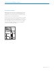
Classic Series Refrigeration Product Information Important product information, including the model and serial number, are listed on the product rating plate. The rating plate is located at the top frame of the unit, inside the door. Refer to the illustration below. If service is necessary, contact Sub-Zero Factory Certified Service with the model and serial number.
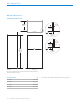
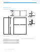
Site Preparation Opening Dimensions STANDARD INSTALLATION 24" (610) OPENING DEPTH 3/4" (19) 3 1/2" (89) TYPICAL FINISHED RETURN TOP VIEW W FRAMELESS CABINETRY 3/4" (19) 3 1/2" (89) FINISHED RETURN 83 3/4" (2127) OPENING HEIGHT SIDE VIEW W OPENING WIDTH TYPICAL FILLER W FRAMED CABINETRY FRONT VIEW NOTE: 3 1/2" (89) finished returns will be visible and should be finished to match cabinetry. Shaded line represents profile of unit.
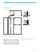
Site Preparation Opening Dimensions FLUSH INSET INSTALLATION 26 3/16" (665) FLUSH INSET DEPTH 5 11/16" 3 1/2" 2 3/16" (56) (89) (145) FINISHED RETURN FINISHED CLEATS TOP VIEW CLEAT 3/4" (19) TYPICAL W FRAMELESS CABINETRY 11/4" 1/4" (6) (32) 5 11/16" 3 1/2" (89) (145) FINISHED RETURN 84" (2134) FLUSH INSET HEIGHT SIDE VIEW W CLEAT FILLER 3/4" (19) TYPICAL W FLUSH INSET WIDTH FRAMED CABINETRY FRONT VIEW NOTE: 3 1/2" (89) finished returns and shaded areas will be visible and should be
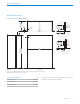
Site Preparation Opening Dimensions DUAL STANDARD INSTALLATION 24" (610) OPENING DEPTH 3/4" (19) 3 1/2" (89) TYPICAL FINISHED RETURN TOP VIEW W FRAMELESS CABINETRY 3/4" (19) 3 1/2" (89) FINISHED RETURN 83 3/4" (2127) OPENING HEIGHT SIDE VIEW W OPENING WIDTH TYPICAL FILLER W FRAMED CABINETRY FRONT VIEW NOTE: 3 1/2" (89) finished returns will be visible and should be finished to match cabinetry. Shaded line represents profile of unit.
Site Preparation Opening Dimensions DUAL FLUSH INSET INSTALLATION 26 3/16" (665) FLUSH INSET DEPTH (56) CLEAT 5 11/16" 3 1/2" 2 3/16" 3/4" (19) (89) (145) FINISHED RETURN FINISHED CLEATS TOP VIEW TYPICAL W FRAMELESS CABINETRY 11/4" 1/4" (6) (32) CLEAT 5 11/16" 3 1/2" (89) (145) FINISHED RETURN 84" (2134) FLUSH INSET HEIGHT SIDE VIEW W FLUSH INSET WIDTH FILLER 3/4" (19) TYPICAL W FRAMED CABINETRY FRONT VIEW NOTE: 3 1/2" (89) finished returns and shaded areas will be visible and sh
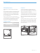
Site Preparation Dual Installation Electrical Requirements If two units are installed side by side, a dual installation kit may be required. Installations without a custom filler strip require a dual installation kit. If a dual installation kit is not specified, a 2" (51) filler strip is recommended between units. Dual installations without a filler strip can only be accomplished using two units with opposite hinges. Refer to the illustrations below.
Site Preparation Plumbing Requirements Preparation Installation must comply with all applicable plumbing codes. Uncrate the unit and inspect for damage. Remove the wood base and discard the shipping bolts and brackets. Remove and recycle packing materials. Do not discard the kickplate, anti-tip brackets, and hardware. The water supply line should be located within the shaded area shown in the illustration below.
Site Preparation Anti-Tip Bracket WARNING To prevent the unit from tipping forward, the anti-tip brackets must be installed. The two anti-tip brackets must be installed exactly 24" (610) from the front of the opening to the back of the brackets and a minimum of 4" (102) from the sides of the opening. This depth will increase to 263/16" (665) for a flush inset installation based on 3/4" (19) thick panels. Failure to properly position the anti-tip brackets will prevent proper engagement.
Site Preparation Anti-Tip Bracket CONCRETE WEDGE ANCHOR INSTALLATION CAUTION 1 Drill a 3/8" (10) diameter hole any depth exceeding the minimum embedment. Clean the hole or drill additional depth to accommodate the drill fines. Always wear safety glasses and use other necessary protective devices or apparel when installing or working with anchors. 2 Assemble the washer and nut flush with the end of anchor to protect threads.
Site Preparation Placement CAUTION Before moving the unit into position, secure door(s) closed and protect any finished flooring. Use an appliance dolly to move the unit near the opening. If the unit has been on its back or side, it must stand upright for a minimum of 24 hours before connecting power. Plug the power cord into the grounded outlet and roll the unit into position. Verify the anti-tip brackets are properly engaged.
Panel Installation Custom Panels For overlay and flush inset applications, custom door and grille panels must be installed. The panel size is critical for a proper fit. To verify panel requirements and dimensions, refer to the Sub-Zero Design Guide at subzero.com/specs. IMPORTANT NOTE: Flush inset applications require a minimum 1/2" (13) reveal on all sides. Finish all sides of the custom panels. They may be visible when the door is open or through the window of glass door models.
Panel Installation Panel Installation DOOR PANELS To install custom door panels, remove the handle side trim molding. Insert a screwdriver tip into the top corner slot on the handle side and pop out the trim. For the drawer, insert a screwdriver tip into the slot on either side of the trim running along the top of the drawer and pop out the trim. Remove the screws and frame. Refer to the illustrations below. The door has a 1/4" (6) frame for the custom panel to slide into.
Panel Installation Panel Installation GRILLE PANEL SIDE PANEL Remove the bottom grille frame by extracting the two lower corner screws from each side of the grille assembly. Refer to the illustration below. When installing a custom side panel, an accessory kit is required and is available through an authorized Sub-Zero dealer. For local dealer information, visit the find a showroom section of our website, subzero.com. Stainless steel side panels are also available from an authorized Sub-Zero dealer.
Installation Alignment LEVELING DOOR ADJUSTMENT Once the unit is in position, turn the front leveling legs clockwise to adjust the height. The rear height adjustment can be made from the front of the roller base. Using a 3/8" socket, turn the 3/8" hex bolt clockwise to raise the unit or counterclockwise to lower. Use the lowest torque setting when using a power drill. Do not turn the rear leveling legs by hand. Refer to the illustration below.
Installation Alignment Completion DOOR ADJUSTMENT GRILLE INSTALLATION To make all other adjustments, loosen the two upper hinge bolts using a 1/2" wrench. Refer to the illustration below. Install the grille assembly and check for proper fit. The grille is designed to rest on the upper door hinge(s) to minimize the reveal between the top of the door and bottom of the grille. To eliminate interference, the grille height can be adjusted.
Installation Completion ANCHORING KICKPLATE INSTALLATION After the unit has been leveled and door adjustment completed, anchor the unit to the opening to ensure a proper fit and secure installation. Reinstall the drain pan and verify it is in the proper position. To anchor the top of the unit, open the grille and install the screws provided through the grille frame into cabinetry. There are several hole locations. Refer to the illustration below. Check for proper door clearance by opening the door.
Installation Completion WATER FILTER BYPASS 90° DOOR STOP If the water filtration system will not be used, it can be placed in water filter bypass mode by removing the water filter. Refer to the illustration below. Follow these steps to remove the water filter: The doors of all models open to 110°. A 90° door stop is provided with the unit (located behind the grille). Additional 90° door stop kits are available through an authorized Sub-Zero dealer.
Refrigeración de la Serie Clásica Contenido 3 Refrigeración Clásica 4 Dimensiones de la abertura 8 Instalación doble 8 Instalación eléctrica 9 Instalación de plomería 9 Preparación 10 Soporte antivuelco 12 Colocación en posición 12 Línea de agua 13 Instalación del panel 16 Alineación 17 Finalización Las características y especificaciones están sujetas a cambios sin previo aviso. Visite subzero.com/specs para obtener la información más actualizada.
Refrigeración de la Serie Clásica Información del producto La información importante del producto, incluidos el modelo y el número de serie de la unidad, se encuentra en la placa de datos del producto. La placa de datos se encuentra en el marco superior de la unidad, en el interior de la puerta. Consulte la siguiente ilustración. Si necesita servicio, póngase en contacto con el centro de servicio autorizado de Sub-Zero y tenga a la mano el modelo y número de serie de la máquina.
Preparación del sitio Dimensiones de abertura INSTALACIÓN ESTÁNDAR 24" (610) PROFUNDIDAD DE LA ABERTURA 3/4" (19) TÍPICA 3 1/2" (89) TUBO DE RETORNO ACABADO VISTA SUPERIOR W GABINETES SIN MARCOS 3/4" (19) 3 1/2" (89) TUBO DE RETORNO ACABADO 83 3/4" (2127) ALTURA DE LA ABERTURA VISTA LATERAL W ANCHO DE LA ABERTURA TÍPICA RELLENO W GABINETES ENMARCADOS VISTA FRONTAL NOTA: Los tubos de retorno de 3 1/2" (89) con acabados y las áreas sombreadas se podrán ver y se deben terminar para que se ajus
Preparación del sitio Dimensiones de abertura INSTALACIÓN EMPOTRABLE 26 3/16" (665) PROFUNDIDAD DE LA INSTALACIÓN EMPOTRABLE 5 11/16" 3 1/2" 2 3/16" (56) CORNAMUSA (145) (89) TUBO DE RETORNO ACABADO CORNAMUSAS TERMINADAS VISTA SUPERIOR 3/4" (19) TÍPICA W GABINETES SIN MARCOS 11/4" 1/4" (6) (32) 5 11/16" 3 1/2" CORNAMUSA (145) (89) TUBO DE RETORNO ACABADO 84" (2134) ALTURA DE LA INSTALACIÓN EMPOTRABLE VISTA LATERAL W ANCHO DE LA INSTALACIÓN EMPOTRABLE FILLER 3/4" (19) TÍPICA W GABINET
Preparación del sitio Dimensiones de abertura INSTALACIÓN ESTÁNDAR DOBLE 24" (610) PROFUNDIDAD DE LA ABERTURA 3/4" (19) TÍPICA 3 1/2" (89) TUBO DE RETORNO ACABADO VISTA SUPERIOR W GABINETES SIN MARCOS 3/4" (19) 3 1/2" (89) TUBO DE RETORNO ACABADO 83 3/4" (2127) ALTURA DE LA ABERTURA VISTA LATERAL W ANCHO DE LA ABERTURA TÍPICA RELLENO W GABINETES ENMARCADOS VISTA FRONTAL NOTA: Los tubos de retorno de 3 1/2" (89) con acabados se podrán ver y se deben terminar para que se ajusten a los gabinete
Preparación del sitio Dimensiones de abertura INSTALACIÓN DE DOS UNIDADES EMPOTRABLE 26 3/16" (665) PROFUNDIDAD DE LA INSTALACIÓN EMPOTRABLE 5 11/16" 3 1/2" 2 3/16" (56) CORNAMUSA (145) (89) TUBO DE RETORNO ACABADO CORNAMUSAS TERMINADAS VISTA SUPERIOR 3/4" (19) TÍPICA W GABINETES SIN MARCOS 11/4" 1/4" (6) (32) 5 11/16" 3 1/2" CORNAMUSA (145) (89) TUBO DE RETORNO ACABADO 84" (2134) ALTURA EMPOTRABLE VISTA LATERAL W ANCHO DE LA INSTALACIÓN EMPOTRABLE RELLENO 3/4" (19) TÍPICA W GABINETE
Preparación del sitio Instalación doble Requisitos eléctricos Si se instalan dos unidades lado a lado, puede ser necesario un kit de instalación doble. Las instalaciones sin una tira de relleno personalizada requieren un kit de instalación doble. Si el uso de un kit de instalación doble no está especificado, se recomienda utilizar una tira de relleno de 2" (51) entre las unidades.
Preparación del sitio Requisitos de plomería Preparación La instalación debe cumplir con todos los códigos de plomería vigentes. Desembale la unidad e inspeccione si tiene algún daño. Retire la base de madera y deseche los pernos y soportes de transporte. Retire y recicle los materiales de embalaje. No deseche el zócalo, los soportes antivuelco ni las piezas de montaje. La línea del suministro de agua debe colocarse dentro del área sombreada que se muestra en la siguiente ilustración.
Preparación del sitio Soporte antivuelco ADVERTENCIA Para evitar que la unidad se vuelque hacia el frente, deben instalarse los soportes antivuelco. Los dos soportes antivuelco deben estar instalados exactamente a 24" (610) de la parte delantera de la abertura hasta la parte trasera de los soportes y un mínimo de 4" (102) desde los lados de la abertura. Esta profundidad se incrementará a 263/16" (665) para una instalación empotrable al ras con paneles con 3/4" (19) de grosor.
Preparación del sitio Soporte antivuelco INSTALACIÓN DE LAS ANCLAS DE CUÑA PARA CONCRETO 1 Haga un orificio de 3/8" (10) de diámetro con una profundidad superior al empotrado mínimo. Limpie el orificio o continúe taladrando para hacer el orificio más profundo y que quepan los residuos en él. 2 Coloque la arandela y la tuerca al nivel del extremo del ancla para proteger las roscas. Inserte el ancla a través del material que va a fijar hasta que la arandela quede al ras del material de la superficie.
Preparación del sitio Colocación PRECAUCIÓN Antes de mover la unidad a su posición, asegúrese de que las puertas estén cerradas y proteja cualquier suelo con acabado. Use una plataforma rodante para mover la unidad cerca de la abertura. Si la unidad ha estado o está acostada o de lado, debe ponerla de pie y dejarla así durante un mínimo de 24 horas antes de conectarla al suministro eléctrico. Conecte el cable de alimentación a la conexión a tierra y coloque la unidad en su sitio.
Instalación de los paneles Paneles personalizados Para aplicaciones revestibles y empotrables, es necesario instalar las puertas personalizadas y los paneles de rejilla. El tamaño del panel es fundamental para un buen ajuste. Para verificar los requisitos y dimensiones del panel, consulte la Guía de diseño de Sub-Zero en subzero.com/specs. AVISO IMPORTANTE: Las aplicaciones empotrables al ras requieren de un margen mínimo de 1/2" (13) en todos los lados.
Instalación de los paneles Paneles personalizados PANELES DE PUERTA Para instalar los paneles de puerta personalizados, retire la moldura del ribete del lado de la manija. Inserte la punta del destornillador en la ranura de la esquina superior del lado de la manija y saque el ribete. Para el cajón, inserte la punta del destornillador en la ranura en cada lado del ribete que recorre la parte superior del cajón y saque el ribete. Quite los tornillos y el marco. Revise las siguientes ilustraciones.
Instalación de los paneles Paneles personalizados PANEL DE REJILLA PANEL LATERAL Para quitar el marco de la rejilla inferior extraiga los tornillos de las dos esquinas inferiores de cada lado de la rejilla. Consulte la siguiente ilustración. Para instalar un panel lateral personalizado, necesitará un kit de accesorios, disponible a través de un distribuidor autorizado de Sub-Zero.
Instalación Alineación NIVELACIÓN AJUSTE DE LA PUERTA Una vez que la unidad está en posición, gire las patas niveladoras delanteras en sentido de las manecillas del reloj para ajustar la altura. El ajuste de la altura de la parte trasera se puede realizar desde la parte delantera de la base rodante. Con una llave de vaso de 3/8" gire 3/8" el perno hexagonal en sentido de las manecillas del reloj para levantar la unidad o en sentido opuesto a las manecillas del reloj para bajarla.
Instalación Alineación Finalización AJUSTE DE LA PUERTA INSTALACIÓN DE LA REJILLA Para hacer todos los demás ajustes, afloje los dos pernos de la bisagra superior con una llave de 1/2". Consulte la siguiente ilustración. Instale el conjunto de la rejilla y compruebe que se ajusta adecuadamente. La rejilla está diseñada para descansar en la bisagra (o bisagras) superior de la puerta para minimizar la vista entre la parte superior de la puerta y la parte inferior de la rejilla.
Instalación Finalización ANCLAJE INSTALACIÓN DEL ZÓCALO Después de nivelar la unidad y completar el ajuste de la puerta, fije la unidad a la abertura para asegurarse de que esté bien ajustada y la instalación sea segura. Vuelva a instalar la bandeja de drenaje y compruebe que esté bien puesta. Para fijar la parte superior de la unidad, abra la rejilla e instale los tornillos suministrados, en los gabinetes a través del marco de la rejilla. Hay orificios en varios lugares.
Instalación Finalización DESVIACIÓN DEL FILTRO DE AGUA TOPE PARA PUERTA A 90° Si no va a utilizar el sistema de filtrado, puede colocarlo en el modo de desvío del filtro de agua mediante la extracción del filtro de agua. Consulte la siguiente ilustración. Siga estos pasos para extraer el filtro de agua: Las puertas de todos los modelos abren a 110°. Un tope de para puerta a 90° se proporciona con la unidad (éste se encuentra detrás de la rejilla).
Réfrigération série Classic Table des matières 3 Réfrigération série Classic 4 Dimensions de l’ouverture 8 Installation double 8 Électricité 9 Plomberie 9 Préparation 10 Support antibasculement 12 Emplacement 12 Conduite d’alimentation en eau 13 Installation des panneaux 16 Alignement 17 Achèvement Les caractéristiques et les spécifications peuvent être modifiées en tout temps sans préavis. Visitez subzero.com/specs pour obtenir les renseignements les plus récents.
Réfrigération série Classic Renseignements sur le produit Des renseignements importants sur le produit, y compris les numéros de modèle et de série, se trouvent sur la plaque signalétique du produit. La plaque signalétique est située sur le cadre supérieur de l’unité à l’intérieur de la porte. Reportez-vous à l’illustration ci-dessous. Si vous avez besoin de service, communiquez avec le service Sub-Zero certifié par l’usine avec les numéros de modèle et de série.
Préparation du site Dimensions de l’ouverture INSTALLATION STANDARD 24 PO (610) PROFONDEUR DE L’OUVERTURE 3/4 3 1/2 PO (89) PO (19) TYPIQUE RETOUR FINI VUE DE DESSUS W ARMOIRE SANS CADRE 3/4 3 1/2 PO (89) RETOUR FINI 83 3/4 PO (2 127) HAUTEUR DE L’OUVERTURE VUE DE PROFIL W PO (19) TYPIQUE MATÉRIAU DE REMBLAYAGE W LARGEUR DE L’OUVERTURE ARMOIRE ENCADRÉE VUE DE FACE REMARQUE : Les retours finis de 3 1/2 po (89) seront visibles et doivent être finis pour s’agencer aux armoires.
Préparation du site Dimensions de l'ouverture INSTALLATION À AFFLEUREMENT 26 3/16 PO 3 1/2 PO (665) PROFONDEUR DE L’AFFLEUREMENT (89) (56) TAQUET 5 11/16 PO 2 3/16 PO 3/4 PO (19) TYPIQUE (145) RETOUR FINI TAQUETS FINIS VUE DE DESSUS W ARMOIRE SANS CADRE 1/4 PO (6) 11/4 PO (32) 3 1/2 PO (89) TAQUET MATÉRIAU DE REMBLAYAGE 3/4 PO (19) TYPIQUE 5 11/16 PO (145) RETOUR FINI 84 PO (2 134) HAUTEUR DE L’AFFLEUREMENT VUE DE PROFIL W W LARGEUR DE L’AFFLEUREMENT ARMOIRE ENCADRÉE VUE DE FACE
Préparation du site Dimensions de l’ouverture INSTALLATION DOUBLE STANDARD 24 PO (610) PROFONDEUR DE L’OUVERTURE 3/4 3 1/2 PO (89) PO (19) TYPIQUE RETOUR FINI VUE DE DESSUS W ARMOIRE SANS CADRE 3/4 3 1/2 PO (89) RETOUR FINI 83 3/4 PO W LARGEUR DE L’OUVERTURE (2 127) HAUTEUR DE L’OUVERTURE PO (19) TYPIQUE MATÉRIAU DE REMBLAYAGE W ARMOIRE ENCADRÉE VUE DE PROFIL VUE DE FACE REMARQUE : Les retours finis de 3 1/2 po (89) seront visibles et doivent être finis pour s’agencer aux armoires.
Préparation du site Dimensions de l’ouverture INSTALLATION DOUBLE À AFFLEUREMENT 26 3/16 PO (665) PROFONDEUR DE L’AFFLEUREMENT 2 3/16 3 1/2 PO (89) TAQUET 5 11/16 PO PO (56) 3/4 PO (19) TYPIQUE (145) RETOUR FINI TAQUETS FINIS VUE DE DESSUS W ARMOIRE SANS CADRE 1/4 PO (6) 11/4 PO (32) 3 1/2 PO (89) TAQUET MATÉRIAU DE REMBLAYAGE 3/4 PO (19) TYPIQUE 5 11/16 PO (145) RETOUR FINI 84 PO (2 134) HAUTEUR DE L’AFFLEUREMENT VUE DE PROFIL W LARGEUR DE L’AFFLEUREMENT W ARMOIRE ENCADRÉE VUE DE F
Préparation du site Installation double Exigences électriques Si deux unités sont installées côté à côte, une trousse d’installation double pourra être requise. Les installations sans languette de remplissage personnalisée nécessitent une trousse d’installation double. Si une trousse d’installation double n’est pas précisée, une languette de remplissage de 2 po (51) est recommandée entre les unités.
Préparation du site Exigences de plomberie Préparation L’installation doit se conformer à tous les codes de plomberie applicables. Sortez l’unité de la boîte et examinez-la pour vous assurer qu’elle n’est pas endommagée. Retirez la base en bois et jetez les boulons et les supports d’expédition. Retirez et recyclez les matériaux d’emballage. Ne jetez pas la plaque de protection, les supports antibasculement et la quincaillerie.
Préparation du site Support antibasculement APPLICATION SUR UN PLANCHER EN BOIS AVERTISSEMENT Pour empêcher l’unité de basculer vers l’avant, les supports antibasculement doivent être installés. Les deux supports antibasculement doivent être installés à une distance exacte de 24 po (610) de l’avant de l’ouverture jusqu’à l’arrière des supports et à une distance d’au moins 4 po (102) des côtés de l’ouverture.
Préparation du site Support antibasculement INSTALLATION DE LA CALE D’ANCRAGE POUR BÉTON MISE EN GARDE 1 Percez un trou de 3/8 po (10) de diamètre de toute profondeur excédant le noyage minimal. Nettoyez le trou ou continuez à percer plus profondément pour accommoder les fines de perçage. Portez toujours des lunettes de sécurité et utilisez d’autres dispositifs ou vêtements de protection nécessaires lors de l’installation ou du travail avec des dispositifs d’ancrage.
Préparation du site Mise en place MISE EN GARDE Avant de mettre l’unité en place, sécurisez la (les) porte(s) en position fermée et protégez tout plancher fini. Utilisez un chariot à appareil pour déplacer l’unité près de l’ouverture. Si l’unité a été posée sur le dos ou le côté, elle doit être mise debout pendant au moins 24 heures avant de relier l’alimentation. Branchez le cordon d’alimentation dans une prise mise à la terre et roulez l’unité en place.
Installation du panneau Panneaux personnalisés Pour les applications à affleurement et à revêtement, des panneaux de porte et de grille personnalisés doivent être installés. La taille du panneau est critique pour obtenir un ajustement approprié. Pour vérifier les exigences et les dimensions des panneaux, reportez-vous au guide de conception Sub-Zero à subzero.com/specs. REMARQUE IMPORTANTE : Les applications à affleurement nécessitent un jeu minimum de ½ po (13) de tous les côtés.
Installation du panneau Panneaux personnalisés PANNEAUX DE PORTE Pour installer des panneaux de porte personnalisés, retirez la moulure de la garniture latérale de la poignée. Insérez la pointe d’un tournevis dans la fente du coin supérieur du côté de la poignée et faites sortir la garniture. Pour le tiroir, insérez la pointe d’un tournevis dans la fente d’un côté ou l’autre de la garniture passant le long de la partie supérieure du tiroir et faites sortir la garniture. Retirez les vis et le cadre.
Installation du panneau Panneaux personnalisés PANNEAU DE LA GRILLE PANNEAU LATÉRAL Retirez le cadre inférieur de la grille en extrayant les vis des deux coins inférieurs de chaque côté de l’assemblage de la grille. Reportez-vous à l’illustration ci-dessous. Lorsque vous installez un panneau latéral personnalisé, une trousse d’accessoire est requise et offerte par un dépositaire Sub-Zero autorisé.
Installation Alignement NIVELLEMENT RÉGLAGE DE LA PORTE Une fois l’unité en position, tournez les pieds de nivellement avant dans le sens horaire pour régler la hauteur. Le réglage de la hauteur arrière peut être effectué à partir de l’avant de la base à roulettes. Au moyen d’une douille de 3/8 po (9), tournez le boulon hexagonal de 3/8 po (9) dans le sens horaire pour relever l’unité ou dans le sens antihoraire pour l’abaisser.
Installation Alignement Achèvement RÉGLAGE DE LA PORTE INSTALLATION DE LA GRILLE Pour effectuer tous les autres réglages, desserrez les deux boulons de la charnière supérieure à l'aide d'une clé de 1/2". Reportez-vous à l'illustration ci-dessous. Installez l’assemblage de la grille et vérifiez son ajustement. La grille est conçue pour être appuyée sur la (les) charnière(s) de porte supérieure(s) afin de minimiser le jeu entre le dessus de la porte et le bas de la grille.
Installation Achèvement ANCRAGE INSTALLATION DE LA PLAQUE DE PROTECTION Une fois l’unité mise au niveau et le réglage de la porte terminé, ancrez l’unité à l’ouverture pour assurer un ajustement adéquat et sécuriser l’installation. Réinstallez la cuvette d’égouttement et vérifiez qu’elle se trouve à la bonne position. Pour ancrer la partie supérieure de l’unité, ouvrez la grille et installez les vis fournies à travers le cadre de la grille dans les armoires. Il y a plusieurs emplacements de trous.
Installation Achèvement DÉRIVATION DU FILTRE À EAU BUTÉE DE PORTE DE 90° Si le système de filtration d’eau n’est pas utilisé, il peut être mis en mode de dérivation du filtre à eau en retirant le filtre à eau. Reportez-vous à l’illustration ci-dessous. Suivez ces étapes pour retirer le filtre à eau : Les portes de tous les modèles s’ouvrent jusqu’à 110°. Une butée de porte de 90° est fournie avec l’unité (située derrière la grille).
SUB-ZERO, INC. P.O. BOX 44848 MADISON, WI 53744 9045824 REV-C 6 / 2022 SUBZERO.COM 800.222.