
Manual
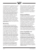
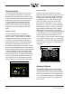
Table Of Contents

Model 5330 User Guide Issue 1, July 2018
Studio Technologies, Inc. Page 9
Installation
In this section the Model 5330 will be in-
stalled and signals interconnected. The
one-rack-space (1U) unit will be mounted in
an equipment rack. On the back panel ana-
log audio input and output connections will
be made using 3-pin male and female XLR
connectors. An Ethernet data connection will
be made using a standard RJ45 patch cable.
Also on the back panel, AC mains power will
be connected by means of a detachable cord
set that is compatible with the unit’s 3-pin
IEC 320 C14 inlet connector. On the front
panel a 3-conductor (stereo) 3.5 mm jack
allows access to audio inputs 1 and 2. Also
on the front panel are 3-conductor 3.5 mm
and ¼-inch jacks that provide access to the
2-channel (stereo) headphone output.
System Components
The shipping carton contains a Model 5330
Flex-Use Dante Audio Interface, a copy of
the user guide, and an AC mains cord suit-
able for use in North America and Japan.
When installation will take place in a different
geographic location your dealer or distributor
should provide a suitable AC mains cord.
Locating the Unit
Providing convenient access to the front-
panel controls and connectors is the pri-
mary focus when selecting a Model 5330
mounting location. It’s expected that users
will need to frequently access the unit so
selecting a convenient location will greatly
aid the operating experience. The selected
mounting location must be within the 100-
meter (325-foot) twisted pair Ethernet cable
limitation. But that can be overcome by using
a fiber-optic interconnection between the
Model 5330-related Ethernet switch and the
other Ethernet switches in the related local-
area-network (LAN). Access to a source of
AC mains power is also required. But that
isn’t expected to be a problem as it is typi-
cally available as part of a rack enclosure’s
resources.
Mounting
Once a mounting location has been selected
installation can begin. The Model 5330 re-
quires one space (1.75 vertical inches or 1U)
in a standard 19-inch (48.3 cm) equipment
rack. Secure the unit into the equipment rack
using four mounting screws, two per side.
Ethernet Connection
An Ethernet connection that supports
100BASE-TX (100 Mb/s over twisted-pair) is
required for the Model 5330’s Dante audio-
over-Ethernet connectivity. A 10BASE-T
connection is not sufficient for Model 5330
operation. A 1000BASE-T (“GigE”) connec-
tion is not supported unless it can automati-
cally “fall back” to 100BASE-TX operation.
The 100BASE-TX Ethernet connection is
made by way of an RJ45 receptacle that is
located on the Model 5330’s back panel.
This allows connection by way of a standard
Ethernet twisted-pair cable and associated
RJ45 plug. The Model 5330’s Ethernet inter-
face supports auto MDI/MDI-X, eliminating
the need to use a crossover or “reversing”
cable.
Figure 3. Ethernet connection (back panel)