
Manual


Model 5205 User Guide Issue 2, August 2017
Studio Technologies, Inc. Page 9
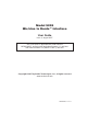
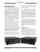
Model 5205
Mic/Line to Dante Interface
of the 3-pin male XLR mating connector. If
this connection arrangement results in hum
or noise it may be effective to try connect-
ing signal + (high) to pin 2 and signal com-
mon/shield only to pin 3.
Dante
Configuration
Several Model 5205’s Dante-related param-
eters can be configured. These configura-
tion settings will be stored in non-volatile
memory within the Model 5205’s circuitry.
Configuration will typically be done with the
Dante Controller software application which
is available for download free of charge at
www.audinate.com. Versions of Dante Con-
troller are available to support Windows®
and OS X® operating systems. The Model
5205 uses the Ultimo 2-input/2-output inte-
grated circuit to implement the Dante archi-
tecture. However, only the two transmitter
(output) channels are utilized. This dictates
which parameters can be configured and
what choices are available.
The two transmitter channels associated
with the Model 5205’s Dante interface
must be assigned to the desired receiver
channels. Within Dante Controller a “sub-
scription” is the term used for routing a
transmitter flow (a group of output chan-
nels) to a receiver flow (a group of input
channels). The number of transmitter flows
associated with an Ultimo integrated circuit
is limited to two. These can either be uni-
cast, multicast, or a combination of the two.
The Model 5205 will support audio sample
rates of 44.1, 48, 88.2, and 96 kHz with a
limited selection of pull-up/pull-down values.
The Model 5205 can serve as the clock
master for a Dante network but in most
cases it will be configured to “sync” to
another device.
The Model 5205 has a default Dante de-
vice name of ST-M5205 and a unique suf-
fix. The suffix identifies the specific Model
5205 that is being configured. The suffix’s
actual alpha and numeric characters relate
to the MAC address of the Ultimo integrat-
ed circuit. The two Dante transmitter chan-
nels have default names of Ch1 and Ch2.
Using Dante Controller the default device
name and channel names can be revised
as appropriate for the specific application.
Operation
At this point an Ethernet connection with
Power-over-Ethernet (PoE) capability
should have been made. Alternately, a
midspan power injector, in “series” with the
Ethernet connection, should have been put
into place. The Model 5205’s Dante con-
figuration settings should have been se-
lected using the Dante Controller software
application. At a minimum the two Dante
transmitter channels should have been
routed to receiver channels on an associ-
ated device. Analog signal sources should
have been connection to the two mic/line
inputs. Normal Model 5205 operation can
now begin.
Initial Operation
The Model 5205 will begin to function as
soon as a Power-over-Ethernet (PoE)
power source is connected. However, full
operation may take 20 seconds or longer
to begin. Upon initial power up the four
status LEDs located on the back panel will
begin to light. The USB LED on the back
panel and the P48, gain, and meter LEDs