
Manual


Issue 2, August 2017 Model 5205 User Guide
Page 8 Studio Technologies, Inc.
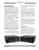
Model 5205
Mic/Line to Dante Interface
A set of mounting brackets is available to
allow a Model 5205 to be attached to the
underside of a desk, table, broadcast set,
or other flat surface. Contact Studio Tech-
nologies for details.
Connections
In this section signal interconnections
will be made using the connectors located
on the back panel of the Model 5205.
An Ethernet data connection with Power-
over-Ethernet (PoE) capability will be
made using either a standard RJ45 patch
cable or an etherCON protected RJ45
plug. Microphone or line-level signal
sources will be connected using two cable-
mounted 3-pin male XLR connectors.
Ethernet Connection
A 100BASE-TX Ethernet connection that
supports Power-over-Ethernet (PoE) is
required for Model 5205 operation. This
one connection will provide both the Ether-
net data interface and power for the Model
5205’s circuitry. A 10BASE-T connection is
not sufficient and a 1000BASE-T (“GigE”)
connection is not supported unless it can
automatically “fall back” to 100BASE-TX
operation. For PoE-supporting Ethernet
switch power management the Model
5205 will enumerate itself as a PoE class 2
device.
The Ethernet connection is made by way
of a Neutrik etherCON protected RJ45
connector that is located on the back panel
of the Model 5205. This allows connection
by way of a cable-mounted etherCON
plug or a standard RJ45 plug. The Model
5205’s Ethernet interface supports auto
MDI/MDI-X so that most cabling implemen-
tations will be correctly supported without
requiring a “cross-over” or “reversing”
cable.
Ethernet Port without PoE
As previously discussed in this guide, the
Model 5205 was designed such that the
Ethernet connection will provide both data
and Power-over-Ethernet (PoE) power.
There may be situations where the associ-
ated Ethernet switch does not provide
PoE power. In these cases an external
PoE midspan power injector can be used.
As long as the midspan power injector
is 802.3af-compatible it should function
correctly. Midspan units are available
from a variety of sources, including Studio
Technologies.
Mic/Line Inputs
The two mic/line inputs are intended for
connection with balanced microphone or
line-level analog audio signal sources.
Typically these sources will be associated
with professional audio equipment such
as dynamic, condenser, or ribbon micro-
phones, audio consoles, video storage and
playback systems, wireless microphone
receivers, and audio testing equipment.
The Model 5205 provides two 3-pin female
XLR connectors for interfacing analog au-
dio signals with the mic/line inputs. For bal-
anced signals pin 2 should be connected
to signal + (high) and pin 3 should be sig-
nal – (low). Pin 1 should be connected to
the shield of the interconnecting cable.
Unbalanced signals can also be connect-
ed. In most cases signal + (high) should
be connected to pin 2 and common/shield
should be connected to both pins 1 and 3