
Manual


Model 5205 User Guide Issue 2, August 2017
Studio Technologies, Inc. Page 11
Model 5205
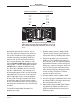
Mic/Line to Dante Interface
Balanced and unbalanced signals with a
wide range of nominal levels can be suc-
cessfully connected.
As expected, a signal connected to the
channel 1 input connector is associated
with Dante transmitter (output) channel 1.
A signal connected to the channel 2 mic/
line input connector is associated with
Dante transmitter (output) channel 2.
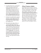
Preamplifier Gain Selection
Two pushbutton switches are associated
with each mic/line input and are used to
locally adjust the gain of the preampli-
fier circuitry. In the 0 dB (line) position the
Model 5205 will provide no (unity) gain. In
this specific case a connected analog sig-
nal that has a level of precisely 0 dBu will
result in a Dante digital audio level of –20
dBFS. (That corresponds to 20 dB less
than the maximum possible level.) Five
other settings allow a gain of 20 to 60 dB,
in 10-dB steps, to be selected.
Select the preamplifier gain such that nor-
mal input signals will cause the five green
LEDs to light. Peak signals can cause the
yellow LEDs to light on occasion. But the
yellow LEDs should never be continuously
lit. The red LED should never light, except
possibly in the case of an extreme peak.
The red LED lighting on a regular basis
indicates that the signal level is at risk of
reaching digital 0 (0 dBFS) which is de-
structive to audio quality.
When changing from the 0 dB to the
20 dB gain setting, or vice-versa, a slight
mechanical click or “tick” sound may be
heard coming from within the Model 5205’s
enclosure. This is caused by the changing
state of an electro-mechanical relay that
places a 20 dB attenuator network in to
or out of the signal path.
Note that due to a technical consideration
the exact gain values are slightly different
from the nominal values that are indicated
on the front panel graphics and in most of
the text provided in this guide. As such,
there can be up to a 1-dB difference, high
or low, at some gain settings. This will typi
-
cally have no impact on the performance
or use of the Model 5205. But laboratory or
other precision testing of the Model 5205 will
show these apparent anomalies. Refer to the
Specifications section of this guide for the
exact values.
P48 Phantom Power
To support microphones that require external
power, the Model 5205 can provide a source
of P48 phantom power. Press the P48 but-
ton associated with the desired channel to
locally change the on/off status of the P48
phantom power source. The P48 LED, blue
in color, will light when P48 phantom power
is being provided to the associated mic/line
input connector. For maximum flexibility P48
phantom power is available in all six of the
preamplifier gain settings, including 0 dB
(line). While P48 phantom power would not
typically be needed in the 0 dB (line) setting
it’s still available for special applications. This
can include use with high-sensitivity micro-
phones being used in environments with
high-SPL audio levels.
Remote Configuration of Gain
and P48 Phantom Power
Using the STcontroller application allows
personal computer users to view and adjust
the Model 5205’s preamplifier gain and P48
phantom power on/off status. The application
is available for download on the Studio Tech-
nologies website (www.studio-tech.com).
Its initial release is compatible with the